Floating type connector

A connector, floating type technology, applied in the direction of connection, parts of the connection device, contact parts, etc., can solve problems such as difficult to align the position, and achieve the effect of reducing manufacturing cost, simple shape, and preventing plastic deformation

Active Publication Date: 2012-08-01
KEZ
View PDF4 Cites 21 Cited by
  • Summary
  • Abstract
  • Description
  • Claims
  • Application Information

AI Technical Summary

Problems solved by technology

[0005] As described above, if the connecting member 530 is plastically deformed, it will

Method used


Image

  • Floating type connector
  • Floating type connector
  • Floating type connector

Examples


Embodiment Construction

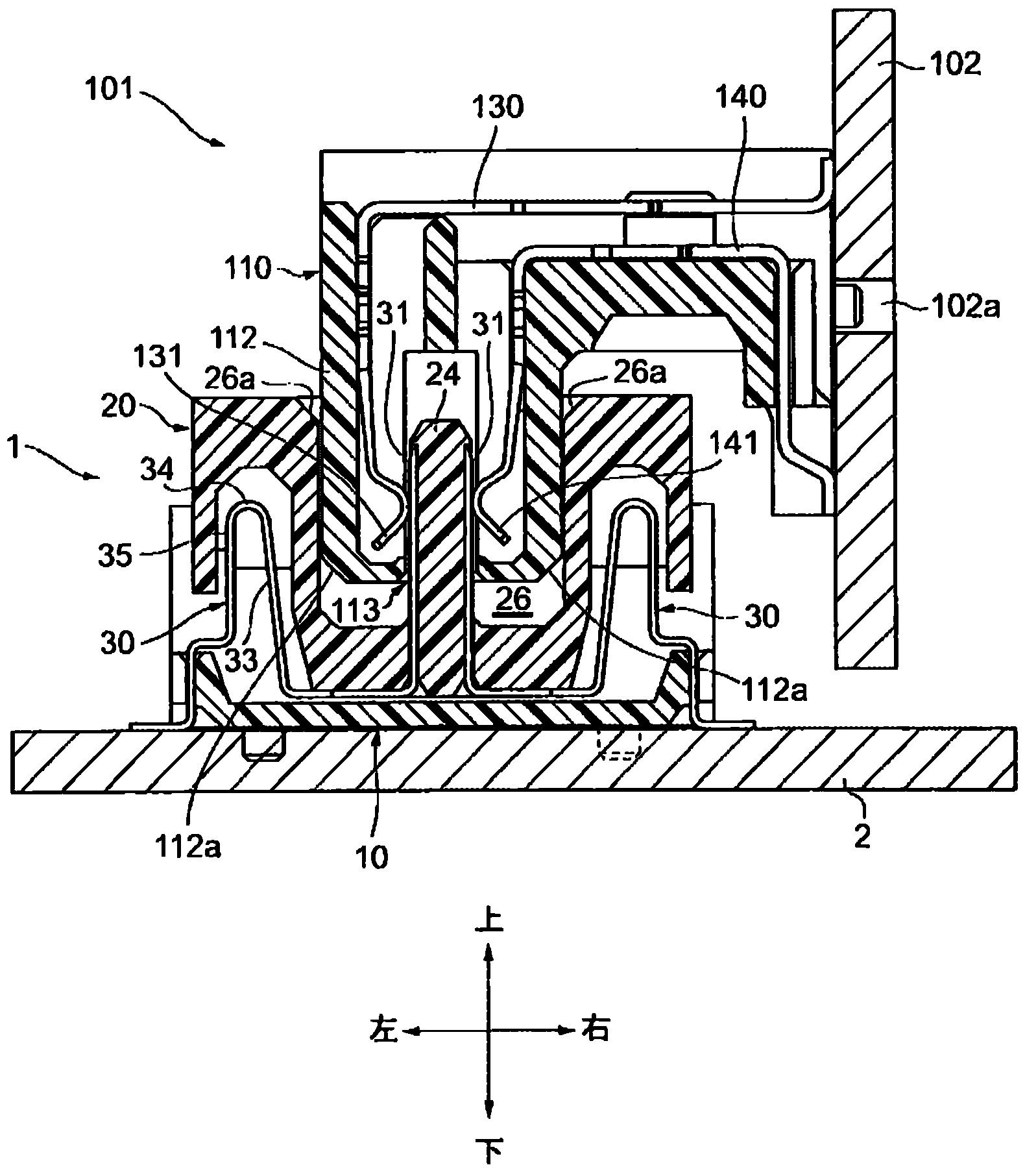
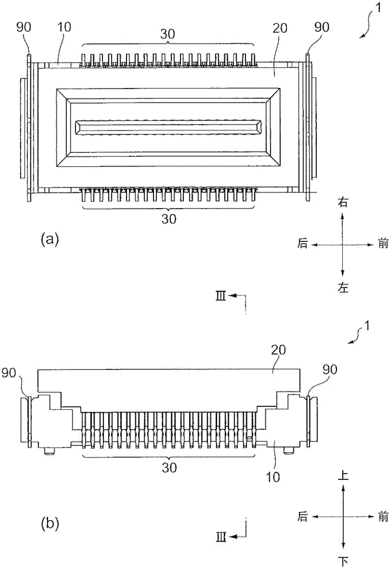
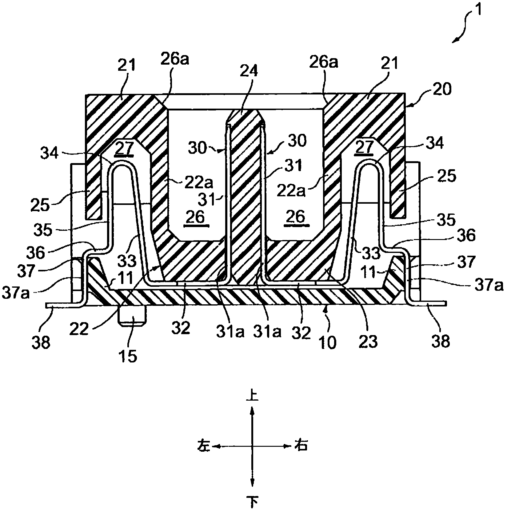
[0030] Embodiments of the present invention will be described below with reference to the drawings. Figure 1 to Figure 8 , Figure 9 (a) and Figure 14 A receptacle connector 1 and its components are shown as one embodiment of the floating connector of the present invention. figure 1 , Figure 9 (b) and Figure 10 ~ Figure 13 A plug connector 101 to be fitted into the receptacle connector 1 and its components are shown. In this embodiment, for the convenience of description, the front and rear, left and right, and up and down directions are defined and described by the arrow directions attached to each figure, but in actual use, they are not limited to these directions. This point is described in the claims. in the same way.

[0031] First, the component structure of the receptacle connector 1 will be described. Such as figure 1 with figure 2 As shown, the socket connector 1 has: a fixed base 10, the lower surface of which is fixed to the socket substrate 2; a mova...


PUM


Abstract

Provided is a floating type connector, comprising a movable substrate (20) having an accepting recess (26), a fixed substrate (10) loading the movable substrate (20) in a free-moving manner, and a connecting member (30), wherein the connecting member (30) comprises a lead portion (38) exposed from the lower surface of the fixed substrate (10), a contact portion (31) located inside the accepting recess (26), and an intermediate portion for connecting the lead portion (38) and the contact portion (31), with the intermediate portion having a curving elastic portion capable of being elastically deformed; the movable substrate (20) comprises a base (21), a central projection portion (22), and an outboard limiting wall (25); the curving elastic portion elastically deforms inside an accepting space (27) of the connecting member (30), thereby making the movable substrate (20) freely move relative to the fixed substrate (10); and the curving elastic portion abuts against the central projection portion (22)/ outboard limiting wall (25), thus to prevent the movable substrate (20) from moving beyond the allowed range.

Description

technical field [0001] The present invention relates to a floating connector, which has a fixed base fixed to a substrate, and a movable base fitted with a counterpart connector, and uses a structure in which the movable base can move freely relative to the fixed base. When the floating connector is mated with the mating connector, even if there is a positional deviation between the substrates on which the connector is mounted, the deviation can be absorbed and the connectors can be reliably connected. Background technique [0002] A connector called a floating connector includes, for example, a fixed base fixed to a substrate, and a movable base having a fitting portion that engages with a counterpart connector, and a connecting member passes through the fixed base and the movable base. . The movable base can move freely relative to the fixed base by utilizing the elastic force of the connecting part. Therefore, for example, when the floating connector is fitted and combin...

Claims


Application Information

Patent Timeline
IPC IPC(8): H01R13/631H01R13/02H01R12/91
Inventor 铃木光雄
Owner KEZ
Why Eureka
Try Eureka