LED driver

A technology of LED driver and rectifier bridge, applied in the field of LED lamp driver

Inactive Publication Date: 2012-08-01
MLS
View PDF6 Cites 0 Cited by
  • Summary
  • Abstract
  • Description
  • Claims
  • Application Information

AI Technical Summary

Problems solved by technology

[0003]1. The circuit structure is complex and the failure rate is high
When one of the electronic components fails, it will cause the driver to fail or even be scrapped, resulting in a shortened service life of the product and great waste
[0004]2. The cost of the driver is high
Capacitors used in LED drivers are generally expensive, resulting in an increase in the cost of the product
[0005]3. The size of the circuit is large
Due to the large number of electronic components in the circuit, especially the large volume of the capacitor, the volume of the driver is large, which does not meet the requirements of miniaturization of the driver.

Method used


Image

  • LED driver
  • LED driver

Examples


Embodiment Construction

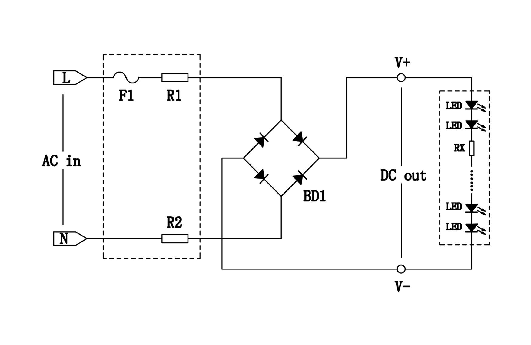
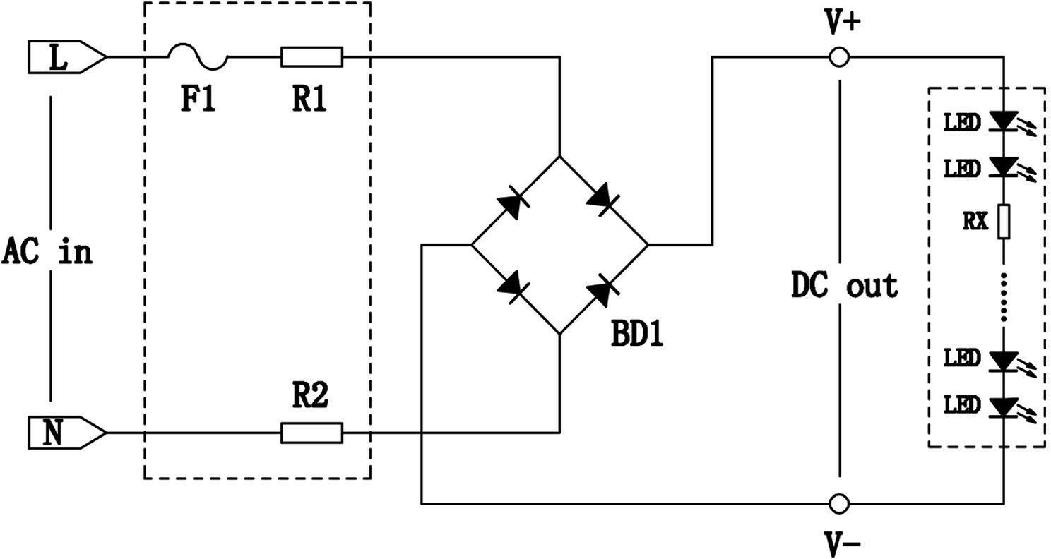
[0015] refer to figure 1 , an LED driver, which consists of a rectifier bridge circuit BD1 and a pre-protection circuit connected to the mains input terminal of the rectifier bridge circuit BD1 (shown in the dotted line box where F1, R1, and R2 are located in the figure), and the LED load is directly connected to the rectifier bridge The output terminal of the LED load (indicated by the dotted line box where LED and RX are located in the figure) is connected in series with a current-limiting resistor RX.

[0016] The pre-protection circuit includes current-limiting resistors R1, R2 and fuse F1 connected in series to the mains input line to protect the circuit.

[0017] The driver of the present invention omits the capacitive filter circuit in the traditional LED drive circuit, overcomes the technical prejudice that the capacitive filter circuit must be added in the traditional LED drive circuit, although the LED load will produce 100Hz flicker after the capacitive filter circ...


PUM


Abstract

The invention discloses an LED driver composed of a rectifier bridge circuit, a front protection circuit connected with the commercial power input end of the rectifier bridge circuit. An LED load is directly connected to the output end of the rectifier bridge circuit; the driver saves a capacitor filter circuit in a conventional LED drive circuit, and overcomes technology prejudice that the capacitor filter circuit must be added in the conventional LED drive circuit. Although the capacitor filter circuit is saved, the LED load can generate 100Hz flashing, but people cannot feel the flashing, the utilization of the LED load can not be affected, the drive circuit is greatly simplified, the cost of the driver is lowered, the service life of the driver is prolonged, and requirement on miniaturization of the driver is met.

Description

technical field [0001] The invention relates to an LED lamp, in particular to a driver for the LED lamp. Background technique [0002] As we all know, the AC frequency in our country is 50Hz. After being rectified by the rectifier bridge, it becomes a pulsating voltage of 100 Hz. When the pulsating voltage of 100 Hz is directly added to the LED lighting load, the LED light will flicker. Therefore, in the LED field, A capacitor filter circuit is added to the LED drive circuit to stabilize the voltage and circuit of the LED lamp, and even achieve an ideal constant current. For this reason, people in the technical field spend a lot of experience and financial resources to find suitable capacitors for LED drive. Design some other circuits around the capacitor to change the performance of the circuit, which will bring inevitable shortcomings, mainly as follows: [0003] 1. The circuit structure is complex and the failure rate is high. When one of the electronic components fails...

Claims


Application Information

Patent Timeline
Patent Type & Authority Applications(China)
IPC IPC(8): H05B37/02
Inventor 林纪良黄赵毓瑞高建利张庆蓉
Owner MLS
Why Eureka
Try Eureka