Simple rotor painting machine

A painting machine and rotor technology, applied in the direction of coating, liquid coating device on the surface, etc., can solve the problems of tired hands of workers, increase of production cost, low work efficiency, etc., and achieve less waste, cost saving, and work high efficiency effect

Inactive Publication Date:
View PDF10 Cites 22 Cited by
  • Summary
  • Abstract
  • Description
  • Claims
  • Application Information

AI Technical Summary

Problems solved by technology

[0002] In the current motor production process, the rotor needs to be coated with insulating paint. However, in the prior art, the rotor is painted manually by workers. The workers need to hold the brush to brush the insulating paint on the rotor one by one, so the labor intensity will be very high. , the hands of the workers will be very tired, and the work efficiency is low, and because the rotor needs to be turned while painting, the coating is not very uniform, and it is easy to produce paint spots, and it will also cause waste of insulating paint, which indirectly increases production. cost

Method used


Image

  • Simple rotor painting machine
  • Simple rotor painting machine

Examples


Embodiment Construction

[0011] The present invention will be further described below in conjunction with the accompanying drawings and specific embodiments, but the present invention is not limited to the following specific embodiments.

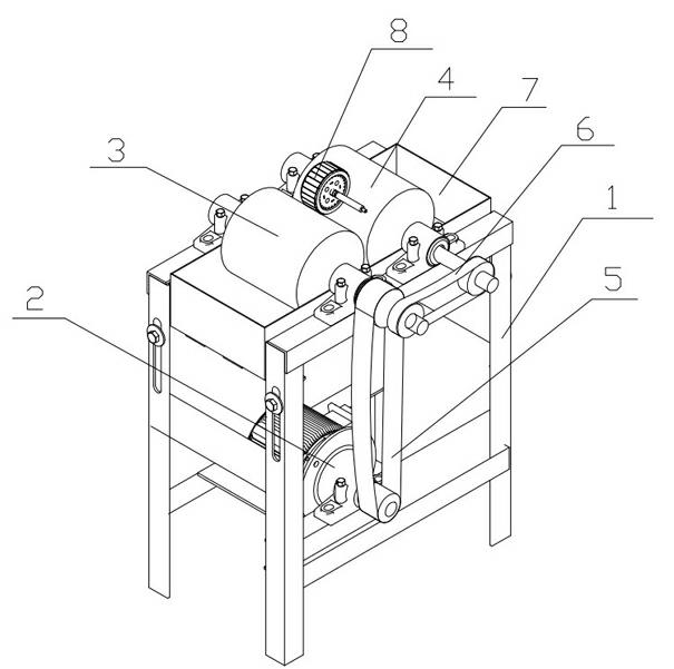
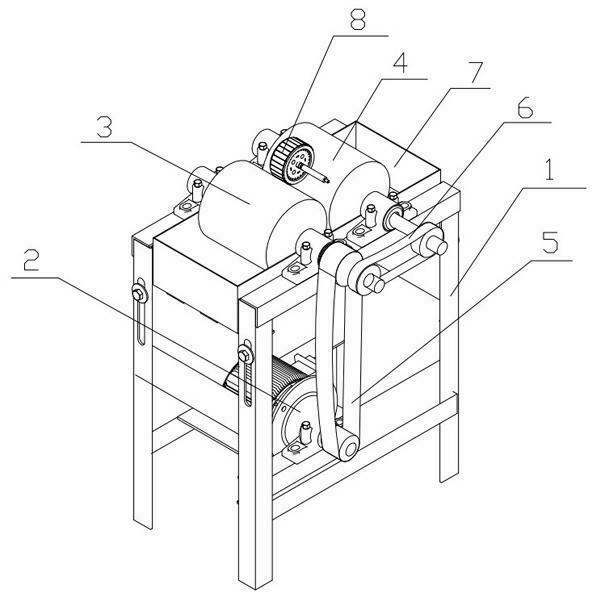
[0012] As shown in the figure: a simple rotor painting machine, which includes a bracket 1, a motor 2, a driving paint roller 3, a driven paint roller 4, a driving belt 5 and a driven belt 6, the motor 2, the driving paint roller 3 and the driven paint roller 4 are all arranged on the support 1, the motor 2 is connected with the driving paint roller 3 through the driving belt 5, the driving paint roller 3 is connected with the driven paint roller 4 through the driven belt 6, and the The simple rotor paint machine also includes a paint box 7 which is arranged on the support 1 and has an open upper end and paint inside. The motor 2 is connected with the driving paint roller 3 through the driving belt 5. The connection means that the driven belt 6 connects the shafts ...


PUM


Abstract

The invention relates to the painting field of a motor rotor, and particularly relates to a simple rotor painting machine. The simple rotor painting machine comprises a bracket (1), a motor (2), a driving painting roller (3), a driven painting roller (4), a driving belt (5) and a driven belt (6), wherein the motor (2), the driving painting roller (3) and the driven painting roller (4) are all arranged on the bracket (1); the motor (2) is connected with the driving painting roller (3) through the driving belt (5); the driving painting roller (3) is connected with the driven painting roller (4) through the driven belt (6); the simple rotor painting machine also comprises a paint box (7) which is arranged on the bracket (1), provided with an opening at the upper end and filled with paint in the internal part, and part of the driving painting roller (3) and part of the driven painting roller (4) are soaked in the paint of the paint box (7). Therefore, the coating machine is high in painting efficiency, uniform in coating and low in cost.

Description

technical field [0001] The invention relates to the field of painting of motor rotors, in particular to a simple rotor painting machine. Background technique [0002] In the current motor production process, the rotor needs to be coated with insulating paint. However, in the prior art, the rotor is painted manually by workers. The workers need to hold the brush to brush the insulating paint on the rotor one by one, so the labor intensity will be very high. , the hands of the workers will be very tired, and the work efficiency is low, and because the rotor needs to be turned while painting, the coating is not very uniform, and it is easy to produce paint spots, and it will also cause waste of insulating paint, which indirectly increases production. cost. Contents of the invention [0003] The technical problem to be solved by the present invention is to provide a simple rotor painting machine with high painting efficiency, uniform painting and low cost. [0004] The tech...

Claims


Application Information

Patent Timeline
Patent Type & Authority Applications(China)
IPC IPC(8): B05C1/02
Inventor 朱守民
Why Eureka
Try Eureka