Device for ventilating a compartment of an aircraft engine

A technology for ventilation equipment and compartments, which is applied in the field of equipment for ventilating compartments, and can solve the problems of increasing the weight and size of aircraft, increasing the weight and size of fire protection systems, etc.

Active Publication Date: 2012-08-15
AIRBUS OPERATIONS (SAS)
View PDF5 Cites 6 Cited by
  • Summary
  • Abstract
  • Description
  • Claims
  • Application Information

AI Technical Summary

Problems solved by technology

However, this necessitates an increase in the weight and size of the fire protection system, and therefore of the aircraft itself, which is disadvantageous

Method used


Image

  • Device for ventilating a compartment of an aircraft engine
  • Device for ventilating a compartment of an aircraft engine
  • Device for ventilating a compartment of an aircraft engine

Examples


Embodiment Construction

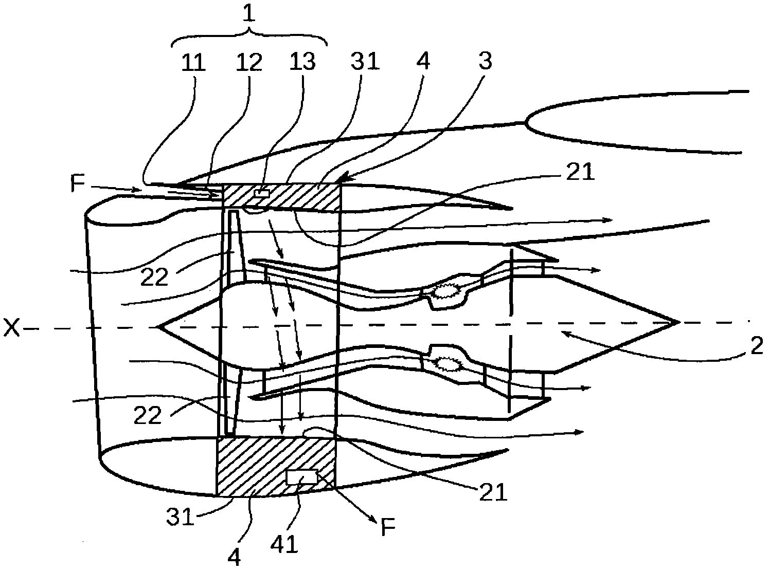
[0023] A description will be given below of a ventilation device 1 for ventilating a compartment 4 of an aircraft engine 2 according to the invention. Such as figure 1 As shown, the engine 2 extends in the axial direction X. In this example, since the engine 2 is mounted in the nacelle 3, the ventilation device 1 according to the invention is arranged to ventilate the compartment 4 formed by the casing 21 of the engine 2 and by the nacelle 3 The hood 31 is defined. Compartment 4, by figure 1 As indicated by the hatching in , an annular volume is formed between the casing 21 of the engine 2 and the nacelle 3 . In this example, the compartment 4 is internally delimited by the fan casing of the engine 2 within which the fan blades 22 are driven.

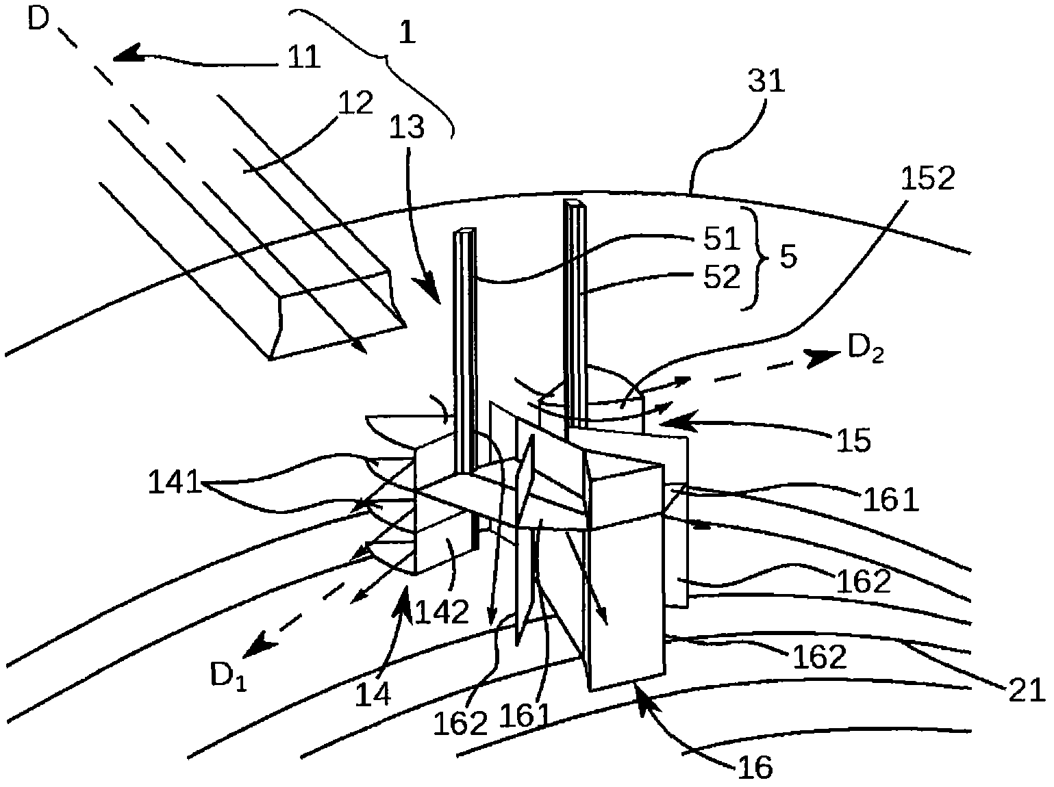
[0024] Such as figure 1 As shown, the ventilation device 1 is located at the upper part of the compartment, and it comprises an air inlet 11 adapted to capture the air flow F outside the engine 2, an air diffuser 12 adapted to guid...


PUM


Abstract

The assembly has a ventilation device (1) for ventilation of a compartment (4) formed between an engine (2) and a nacelle (3). The ventilation device includes an air intake (11) adapted to capture air flow (F) outside the compartment (4), an air diffuser (12) adapted to guide the air flow (F) into the compartment (4), and an air distributor (13) adapted to distribute the air flow (F) within the compartment (4). The air distributor (13) in the device is separated from the air diffuser (12) and positioned within the compartment (4) at distance from the air diffuser (12).

Description

technical field [0001] The present invention relates to the field of ventilation of compartments by circulating an air flow within the compartment, ie here a compartment is defined as a space delimited / delimited by a plurality of partitions. More specifically, the object of the invention is to provide ventilation for at least one aircraft engine compartment by circulating a flow of air drawn from outside the engine. [0002] Aircraft engines conventionally comprise a plurality of compartments which require ventilation, for example in order to cool the components located in each compartment, or in order to renew the air in order to remove any fuel vapors from the compartments. [0003] In order to renew the air in the engine compartment, the air flow must be extracted from outside the compartment, directed into the compartment, and finally the hole air flow is directed in the compartment to achieve the desired purpose (cooling, removal of fuel vapors, etc). For this purpose, ...

Claims


Application Information

Patent Timeline
Patent Type & Authority Applications(China)
IPC IPC(8): B64D33/08
CPCB64D2241/00B64D33/08Y10T137/0536
Inventor Y索默雷尔
Owner AIRBUS OPERATIONS (SAS)
Why Eureka
Try Eureka