
Prefabricated reinforced concrete component with grooves and manufacturing method thereof

A technology of reinforced concrete and a manufacturing method, which is applied to building components, structural elements, manufacturing tools, etc., to achieve the effects of convenient transportation and installation, resource saving and good quality.

Active Publication Date: 2012-08-15
初明进
View PDF6 Cites 39 Cited by
  • Summary
  • Abstract
  • Description
  • Claims
  • Application Information

AI Technical Summary

Problems solved by technology

The connection between prefabricated hollow components is still a weak link in the existing technology

Method used


Image

  • Prefabricated reinforced concrete component with grooves and manufacturing method thereof
  • Prefabricated reinforced concrete component with grooves and manufacturing method thereof
  • Prefabricated reinforced concrete component with grooves and manufacturing method thereof

Examples


Embodiment 1

[0042] Embodiment 1 is a prefabricated reinforced concrete slab member with grooves, such as figure 1 , figure 2 As shown, the longitudinal edge of the plate 11 is arranged with transverse grooves 12, which are arranged alternately with the protrusions 13; the plate 11 has several longitudinal holes 14, and the holes near the longitudinal edge intersect with the transverse grooves 12; the plate 11 is provided with mounting rings 15 . When prefabricated reinforced concrete slab members are used as walls, the length is generally taken as the height of the building, the width is generally taken as a modulus of 300, and the thickness is equal to the thickness of the wall.

[0043] The preparation method of embodiment 1 comprises the following steps:

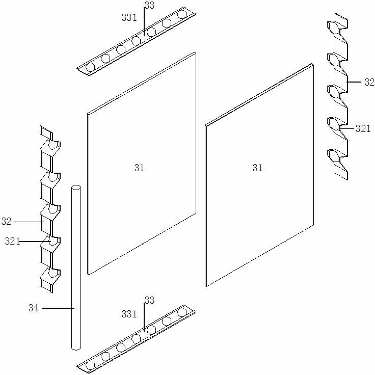
[0044] 1) Arrange the flat bottom form 31, two side forms 32 and two top forms 33 on the production site according to the size of the prefabricated components, such as image 3 , arranging reinforcement cages and suspension rings...

Embodiment 2

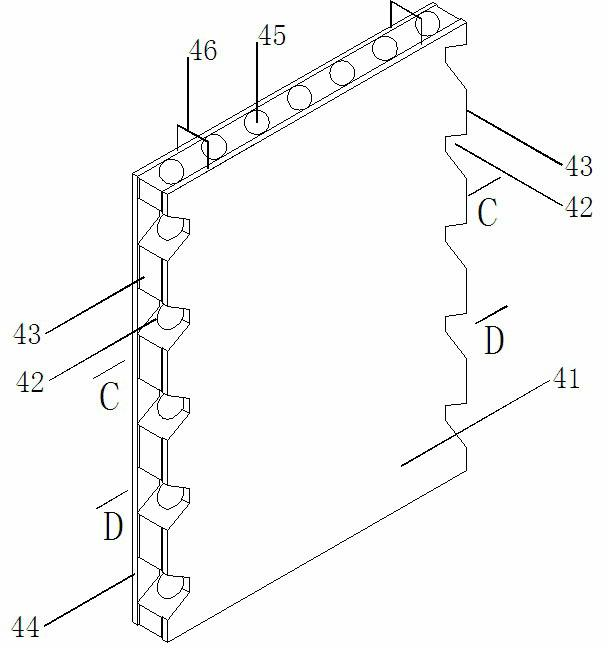
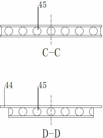
[0050] Embodiment 2 is a prefabricated reinforced concrete T-shaped wall column member with grooves, such as Figure 8 As shown, the longitudinal edge of the T-shaped wall column member 81 is arranged with transverse grooves 82 (at least one longitudinal edge is arranged with transverse grooves), which are arranged alternately with the protrusions 83 on the longitudinal edges; the T-shaped wall column member 81 has several longitudinal holes 84, the hole near the longitudinal edge intersects with the transverse groove 82; the T-shaped wall column member 81 is provided with an installation ring 85. In practical application, the three limbs of the T-shaped wall column adopt the limb lengths that meet the requirements of the building structure. The length of the T-shaped wall column member is generally taken as the story height of the building, and the thickness is generally equal to that of the wall.

[0051] The preparation method of embodiment 2 comprises the following steps:...


PUM


Abstract

The invention relates to a prefabricated reinforced concrete component with grooves and a manufacturing method thereof and belongs to the technical field of components in a prefabricated reinforced concrete structure. The component uses a cored slab prefabricated by reinforced concrete; and transverse grooves are arranged at the vertical edge of the reinforced concrete prefabricated slab at intervals, and are interacted with vertical holes parallel to the surface in the prefabricated slab. The manufacturing method provided by the invention comprises the following steps of: combining templates, such as a bottom die, a top die, a side die, a steel pipe inner die and the like on a production field of prefabricated slabs; arranging reinforcing meshes; then pouring concrete; drawing a steel pipe before hardening the concrete; and dismounting the templates after the concrete reaches to the expected strength. According to the prefabricated reinforced concrete component and the manufacturing method thereof provided by the invention, the industrial level of a building structure is improved, the load-carrying capability is improved, and resources can be saved. The prefabricated reinforced concrete component can be applied to various wall body bearing structures.

Description

technical field [0001] The invention belongs to the technical field of prefabricated reinforced concrete structural components, and in particular relates to a prefabricated reinforced concrete hollow component with transverse grooves on the longitudinal edge which is suitable for assembling integral structures and a manufacturing method thereof. Background technique [0002] During the construction of cast-in-place reinforced concrete structures, there are many on-site fabrications and wet operations, and there are a large number of intermediate links such as formwork projects and scaffolding projects, which waste resources and pollute the environment; the quality of employees and the environment of the construction site have a great impact on the construction quality, bringing Issues of building performance, quality and durability. To change the status quo of cast-in-place reinforced concrete structures, prefabricated concrete structures should be vigorously developed. The...

Claims


Application Information

Patent Timeline
Patent Type & Authority Applications(China)
IPC IPC(8): E04C2/30E04C2/36E04B2/66E04C2/06B28B23/02
CPCB28B7/0082B28B7/186B28B11/12E04C2/06E04C2/322B28B7/22E04C2/30B28B1/00B28B1/14E04B2/84E04B2/8647E04C5/01E04C5/08
Inventor 初明进
Owner 初明进
Learn More