Stereoscopic imaging apparatus
A technology of stereo imaging and imaging device, which is applied in the field of focus adjustment technology and can solve the problems of unsuitability for interview shooting, excessive effort and time, etc.
- Summary
- Abstract
- Description
- Claims
- Application Information
AI Technical Summary
Problems solved by technology
Method used
Image
Examples
no. 5 example
[0035] 7. Fifth Embodiment (Example of a configuration in which the position of the principal point of the imaging optical system is moved, and with this movement, the imaging device is moved in a direction away from the optical axis of the target optical system to perform focus adjustment)
[0036] 8. Modified form of the fifth embodiment (an example of a configuration using a lens whose position of the principal point on the front side hardly moves at the time of focus adjustment as a lens of the imaging optical system)
[0037] 9. Modifications of the first to fifth embodiments
[0038]
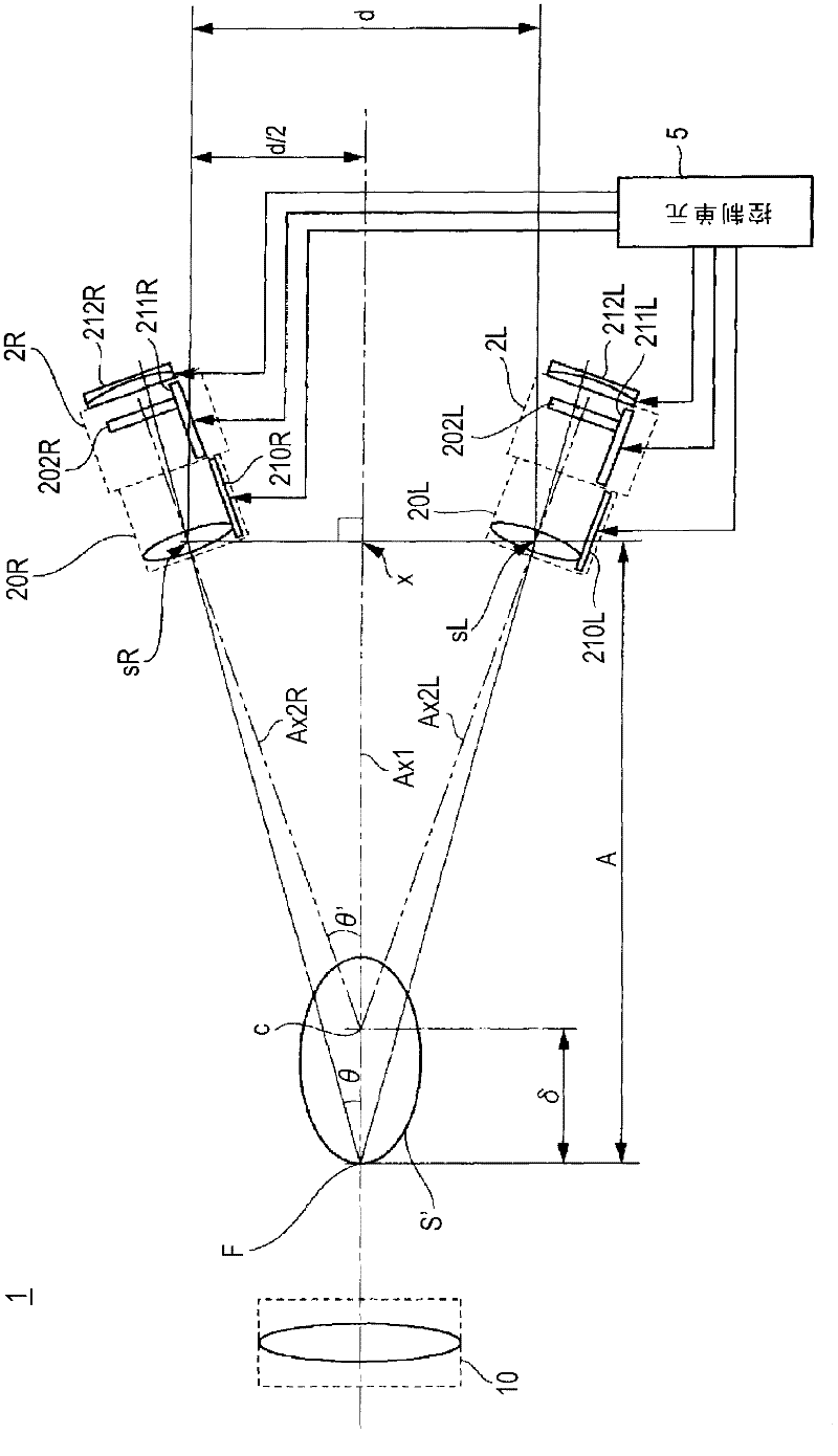
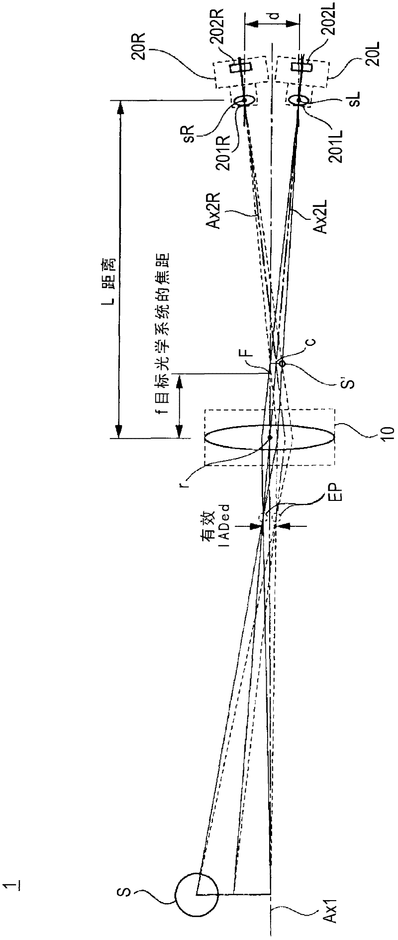
[0039] exist figure 1 , a configuration example of a stereoscopic imaging device 1 according to an embodiment of the present invention is shown. refer to figure 1 The stereoscopic imaging device 1 shown in , the basic configuration and focus adjustment operation common to the first to fifth embodiments described later will be described. The stereoscopic imaging device 1 includes an ob...
no. 1 example
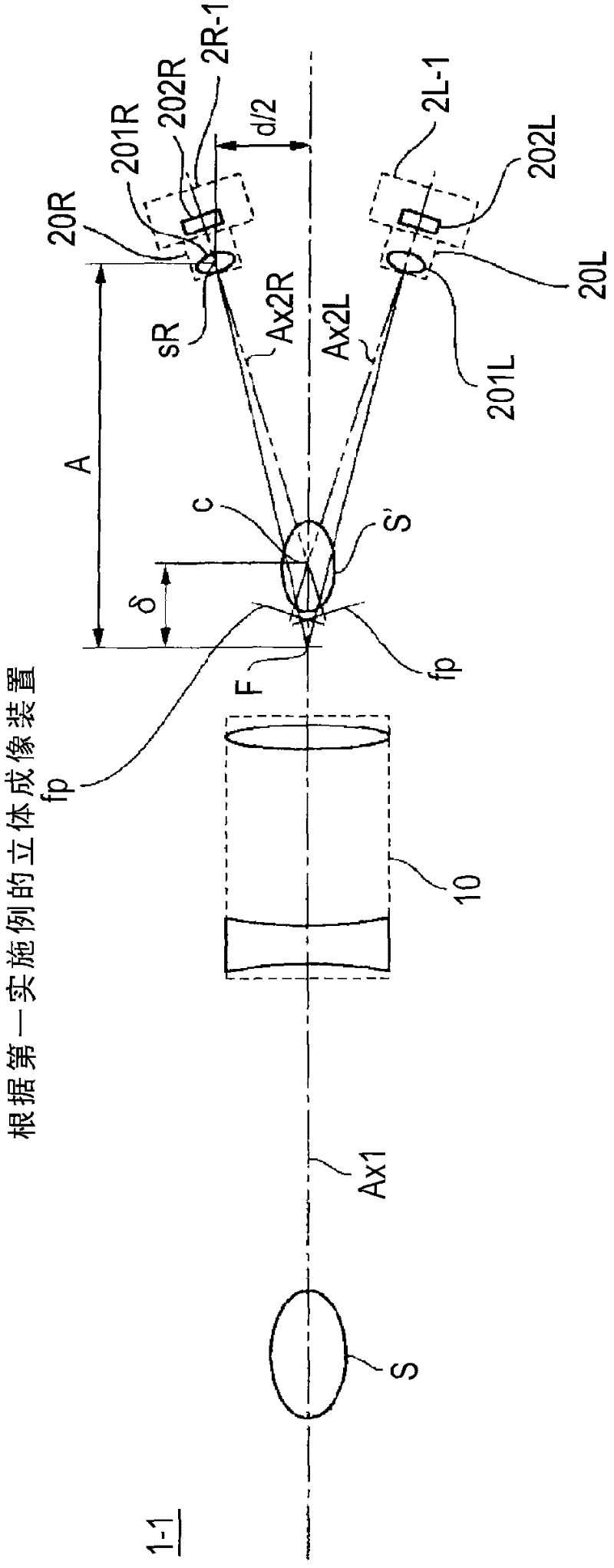
[0065] will refer to Figure 3A and 3B A stereoscopic imaging device 1-1 according to a first embodiment of the present invention will be described. Such as Figure 3A and 3B As shown, the objective optical system 10 includes concave lenses and convex lenses. and figure 1 Similar to the configuration shown in , the imaging sections 2R and 2L are arranged in such a manner that the optical axis Ax2R of the imaging optical system 20R and the optical axis Ax2L of the imaging optical system 20L intersect each other on the optical axis Ax1 of the objective optical system.
[0066] The optical axis Ax2R of the imaging optical system 20R and the optical axis Ax2L of the imaging optical system 20L are made to intersect each other at a position (intersection point c) on the optical axis Ax1 of the objective optical system which is a distance δ from the focal point F. The position of the intersection point c is adjusted to be set within the range in which the aerial image S' is form...
no. 3 example
[0081] will refer to Figures 5A to 5C A stereoscopic imaging device 1-3 according to a third embodiment of the present invention is described. Such as Figures 5A to 5C As shown, in the stereoscopic imaging device 1 - 3 , the imaging sections 2R and 2L are provided in such a manner that the optical axis of the imaging optical system 20R ( 20L) is parallel to the optical axis Ax1 of the object optical system 10 . Further, the imaging optical systems 20R and 20L include convergence angle variable lenses 204R and 204L respectively formed of concave lenses.
[0082] The convergence variable lens 204R ( 204L) is configured to be movable in a direction away from the optical axis Ax1 of the objective optical system 10 with respect to the optical axis Ax2 of the imaging optical system 20 . The angle formed by the optical axis Ax2 of the imaging optical system 20 and the optical axis Ax1 of the objective optical system 10 changes according to the amount of movement of the convergenc...
PUM
 Abstract
Description
Claims
Application Information
 - R&D Engineer
- R&D Manager
- IP Professional
- Industry Leading Data Capabilities
- Powerful AI technology
- Patent DNA Extraction
Browse by: Latest US Patents, China's latest patents, Technical Efficacy Thesaurus, Application Domain, Technology Topic, Popular Technical Reports.
© 2024 PatSnap. All rights reserved.Legal|Privacy policy|Modern Slavery Act Transparency Statement|Sitemap|About US| Contact US: help@patsnap.com


