
Direct-current catenary de-icing method of high-speed electrified railway

A technology for electrified railways and DC ice melting, applied in the installation of electrical components, cables, overhead installations, etc., can solve the problems of large reactive power and low power factor, achieve cost saving, convenient use, and reduce the impact of negative sequence Effect

Active Publication Date: 2012-08-15
ZHUZHOU NAT ENG RES CENT OF CONVERTERS
View PDF7 Cites 13 Cited by
  • Summary
  • Abstract
  • Description
  • Claims
  • Application Information

AI Technical Summary

Problems solved by technology

This document proposes an anti-icing scheme using adjustable reactors during the skylight period. Although this scheme can effectively reduce active power loss, the disadvantage is that the power factor is relatively low (0.28-0.3), and the reactive power injected by the catenary itself into the power system High power, up to 14607kvar / h

Method used


Image

  • Direct-current catenary de-icing method of high-speed electrified railway
  • Direct-current catenary de-icing method of high-speed electrified railway
  • Direct-current catenary de-icing method of high-speed electrified railway

Examples


Embodiment Construction

[0059] The following will clearly and completely describe the technical solutions in the embodiments of the present invention with reference to the accompanying drawings in the embodiments of the present invention. Obviously, the described embodiments are only some, not all, embodiments of the present invention. Based on the embodiments of the present invention, all other embodiments obtained by persons of ordinary skill in the art without making creative efforts belong to the protection scope of the present invention.

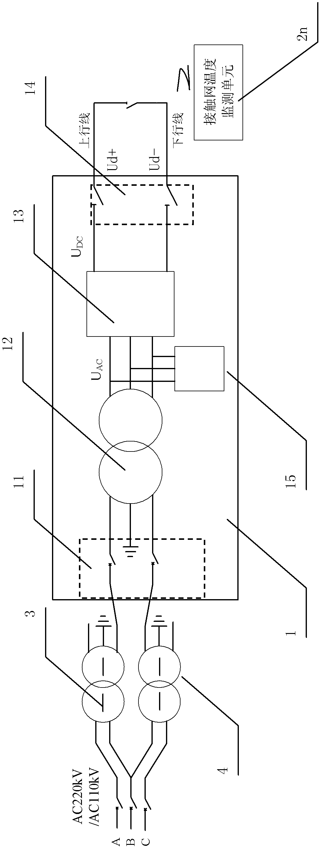
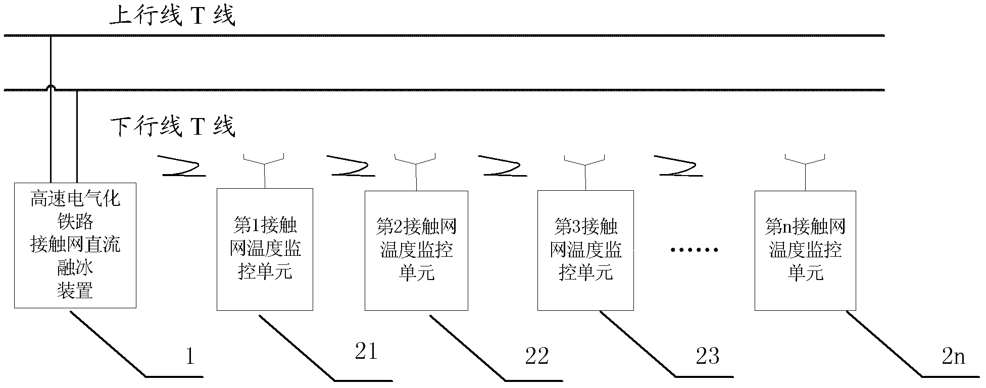
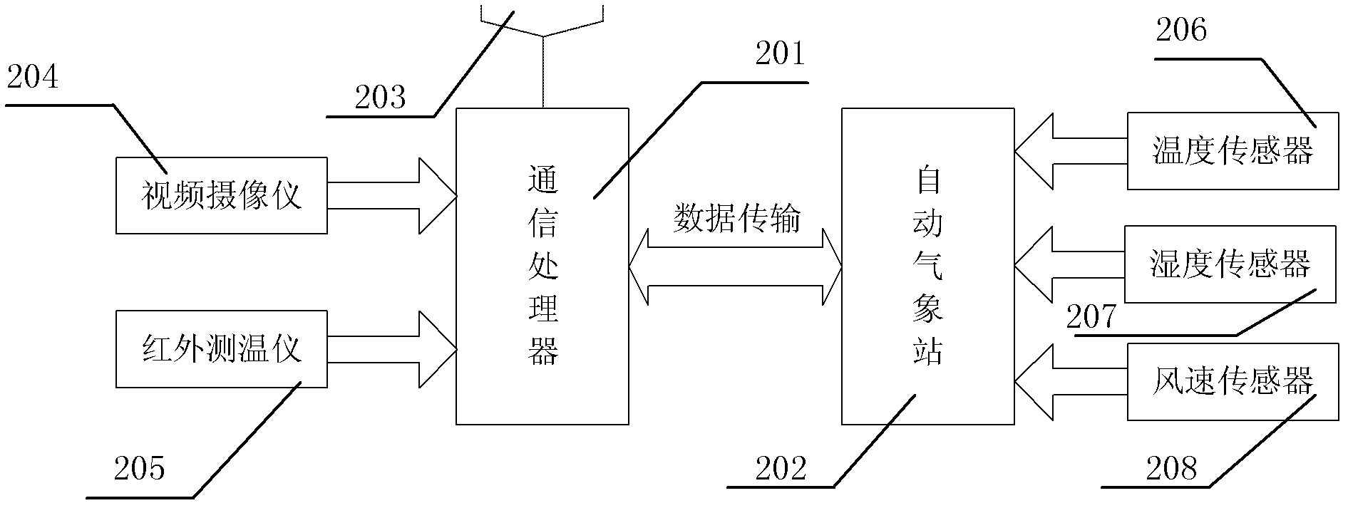
[0060] as attached figure 1 to attach Figure 7 As shown in the figure, a specific embodiment of the method for DC deicing of a high-speed electrified railway catenary of the present invention is provided, and the present invention will be further described below in conjunction with the accompanying drawings and specific embodiments.

[0061] as attached figure 1 Shown is a specific embodiment of a high-speed electrified railway catenary DC deicing device in...


PUM


Abstract

The invention discloses a direct-current catenary de-icing method of a high-speed electrified railway. The direct-current catenary de-icing method comprises direct-current catenary de-icing equipment input and quit processes. The input process comprises the following steps that: when a direct-current de-icing system monitors the icing state of a catenary and puts forward a de-icing demand, corresponding feeder switches and catenary switches are switched off by an electric power control center in a long distance, a substation is switched to be in a direct-current catenary de-icing operation state from a normal traction power supply state, and corresponding direct-current de-icing on-off switches, catenary switches and feeder switches in the substation are closed to input direct-current de-icing equipment. The quit process comprises the following steps that: the de-icing equipment is shut down, the corresponding direct-current de-icing on-off switches, feeder switches and catenary switches are disconnected to break the disconnection between the de-icing equipment and the substation and the catenary, and the corresponding feeder switches and catenary switches are closed to switch the feeder switches to be in a traction power supply state of an electric locomotive. According to the direct-current catenary de-icing method, the concentration and systematization of functions are realized, the operation and maintenance are safe, convenient and efficient, and the installation ways are flexible and changeable.

Description

technical field [0001] The invention relates to a DC ice-melting method applied to power supply lines in the field of electric power systems, in particular to a DC ice-melting method for catenaries of high-speed electrified railways. Background technique [0002] In recent years, my country's electrified railway construction has entered a stage of rapid development, and new high-power AC-DC electric locomotives have gradually become the main model of my country's electrified railways, especially high-speed railways. In particular, the traction power supply system is responsible for providing electric energy to high-speed trains, and is a key factor for the safe, reliable and efficient operation of trains. [0003] However, with the change of global temperature, there have been historically rare ice and snow disasters in southern, central and eastern China, especially in most parts of Hunan, Guizhou and Jiangxi provinces, where power facilities have suffered unprecedented dam...

Claims


Application Information

Patent Timeline
IPC IPC(8): H02G7/16
Inventor 邓建华黄燕艳石二磊王卫安周成周方圆唐亚军吴强张敏段世彦谭胜武陈洁莲沈丁建陶洪亮唐建宇邱文俊吴明水张玉平郭民蔡蔚严树钢
Owner ZHUZHOU NAT ENG RES CENT OF CONVERTERS
Learn More