
Prestress steel rod intelligent anchoring system monitoring dynamic state of strengthening engineering preload

A prestressed steel and anchoring system technology, applied in bridge reinforcement, measuring devices, building reinforcements, etc., can solve the problems of rough loss judgment, low integration, affecting test accuracy, etc., to achieve fast operation and maintenance, and solution results. Precise, wide-ranging effects

Active Publication Date: 2012-06-06
HUNAN UNIV OF SCI & TECH
View PDF0 Cites 0 Cited by
  • Summary
  • Abstract
  • Description
  • Claims
  • Application Information

AI Technical Summary

Problems solved by technology

Its shortcoming is that the webs of many concrete box girder bridges still have different degrees of cracking during construction and operation, especially the webs of long-span prestressed concrete box girder bridges are more obvious
[0004] The aforementioned sensor detection method uses a large number of sensors, and the cost is too high for larger projects, so it is only suitable for scientific research; the aforementioned strain gauge detection method is cumbersome to operate, interferes with construction, is inconvenient, cannot be reused, and is only suitable for small areas Scientific research; the aforementioned steel rod drilling sound wave ranging detection method needs to drill a steel rod and measure the initial length, which requires a flat end face, troublesome operation, and low accuracy; there is also the oil meter control method, which is rough in judging the loss, and its The accuracy is low and the prestress of the bolt cannot be monitored for a long time; the conventional pull-out test can only roughly estimate the bearing capacity of the bolt, and cannot play the role of dynamic monitoring, and it is a destructive test with narrow adaptability
In addition, the detection method of the vertical prestressed tendon tension of the concrete box girder bridge web is based on the characteristics of the concrete box girder bridge and uses corrugated sleeves to pre-embed holes. Affects the test accuracy; its calculation program only has the calculation equation of the vertical prestressed anchorage system, which is not suitable for the pre-tightening force detection of other fastening components such as anchor rods, anchor cables and bolts; It is not high, and more assistive devices must be equipped on site to work

Method used


Image

  • Prestress steel rod intelligent anchoring system monitoring dynamic state of strengthening engineering preload
  • Prestress steel rod intelligent anchoring system monitoring dynamic state of strengthening engineering preload
  • Prestress steel rod intelligent anchoring system monitoring dynamic state of strengthening engineering preload

Examples


Embodiment A

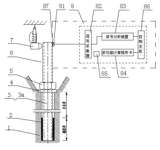
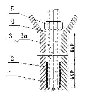
[0038] ①Constructors pre-locate and embed the anchorage system according to the design drawings of the prestressed reinforcement project, and determine the installation position and inclination angle. When the reinforcement project requires the steel rod 3 to be arranged in a curved line, the exposed section 6 of the prestressed steel rod 3a is selected from rigid materials. The threaded steel bar is made; the pre-embedded section of the steel rod 3 is made of steel cables in flexible materials, and the steel cable and the exposed section 6 of the prestressed steel rod 3a pass through the free section of the pre-embedded section of the steel rod 3 at a distance of 150mm from the supporting plate 5 Connection and fixation by means of welding or buckling; the construction process is: drilling holes in reinforcement object 1 or reserving installation positions → installing steel rod 3 → anchoring at the bottom of steel rod 3 → welding or Buckle → tension lock → anti-corrosion prot...

Embodiment B

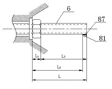
[0042] ①The process of transforming the steel rod 3 into the prestressed steel rod 3a is completed after the construction operation. According to the requirements, the length L of the exposed section 6 of the prestressed steel rod 3a should be greater than 4 times the diameter of the prestressed steel rod 3a, that is, the bottom surface of the nut 5 to the The length of the top end surface of the exposed section 6 of the prestressed steel rod 3a; the prestressed steel rod 3a generally uses a diameter of The precision-rolled threaded steel bar, the supporting nut 5 is 52mm in height, the shape is hexagonal, the distance across the sides is 48mm, and the exposed section of the prestressed steel rod 3a is 6 long L 2 Equal to 152mm, that is, the length L from the bottom surface of the nut 5 to the inner edge of the acceleration sensor 81 2 Equal to 152mm.

[0043] ② The top of the exposed section 6 of the prestressed steel rod 3a is fixedly connected with an acceleration sensor ...


PUM

PropertyMeasurementUnit
diameteraaaaaaaaaa

Abstract

The invention relates to a prestress steel rod intelligent anchoring system monitoring dynamic state of strengthening engineering preload. In the system, a steel rod, a supporting plate and a nut are implanted in a selected strengthening object, the embedded section of the steel rod and the strengthening object are combined and are tensioned into a prestress steel rod, an acceleration sensor and a vibration exciter are arranged at the top end of the exposed section of the prestress steel rod, the acceleration sensor is connected with an intelligent measuring cell, and a signal acquirer, a signal analyzing device, a multifunctional calculation program card, a rechargeable battery and a control main board are built-in in the system, the vibration exciter is utilized to cause the exposed section to vibrate, the control main board is operated, length L2 is input and the intelligent measuring cell is operated to convert a vibration electric signal into a natural frequency spectrum, thus acquiring the preload transmitted to the supporting plate by the prestress steel rod and realizing monitoring of dynamic state of strengthening engineering preload. The invention overcomes the defects that the existing detection method is high in cost and can not realize large-area detection on preload construction quality on site and anchor rod can not work, and the invention is applicable to preload anchoring system strengthening engineering requiring large-area monitoring.

Description

technical field [0001] The invention relates to an intelligent anchoring system for prestressed steel rods which monitors the dynamics of the pretightening force of a reinforcement project. Background technique [0002] The existing prestressed reinforcement engineering technology has been rapidly developed and applied to the structural system of expressways and urban large and medium-span concrete continuous (rigid frame) box girder bridges. It has the advantages of high structural rigidity, smooth driving, less expansion joints, low maintenance costs, and is suitable for various spans. In order to reduce and control the main tensile stress of the box web and prevent the web concrete from cracking, it has become one of the important contents of the design to set the vertical prestressed tendons on the box girder web. Using precision-rolled threaded steel bars as the vertical prestressed tendons of the web of concrete box girders has the advantages of not being bound by wel...

Claims


Application Information

Patent Timeline
Patent Type & Authority Patents(China)
IPC IPC(8): E04G23/02E01D22/00E04C5/12G01L5/00
Inventor 杨滔钟新谷沈明燕
Owner HUNAN UNIV OF SCI & TECH
Learn More