No cycle methanation system

A methanation, non-circulating technology, applied in the field of methanation reaction, can solve the problems of increased feed flow of the reactor, unfavorable installation, disassembly, and high investment, and achieve stable reaction operation, low operating cost and cost, and simplified process system. Effect

Active Publication Date: 2016-08-17
BEIJING HUAFU ENG +2
View PDF7 Cites 0 Cited by
  • Summary
  • Abstract
  • Description
  • Claims
  • Application Information

AI Technical Summary

Problems solved by technology

The cyclic methanation process has at least the following disadvantages: (1) Due to the increase of the feed flow rate of the reactor, the reaction driving force decreases, and the catalyst loading will increase significantly
(2) It is necessary to use a circulating gas compressor, which is difficult to manufacture and requires high investment
(3) Using circulation to control the temperature of the methanation reaction, there is a possibility of overheating
But the high-temperature reactor in the prior art also has at least the following disadvantages: (1) the refractory lining of the existing high-temperature reactor usually has a considerable thickness, which makes the overall volume of the existing high-temperature reactor larger, which is unfavorable for installation , Disassembly
(2) After being subjected to equipment vibration and / or drastic temperature changes, the refractory lining of the existing high-temperature reactor is prone to damage such as cracking and falling off; once the refractory lining is damaged, the strong exothermic reaction will directly damage the high-temperature reactor shell, which may lead to safety accidents
(3) The strong exothermic reaction makes the outlet temperature of the high temperature reactor too high, so the follow-up production equipment used with the high temperature reactor (for example: the outlet pipe of the high temperature reactor, the waste heat boiler for heat recovery, etc.) High temperature resistance, which brings difficulties to the selection and processing of production equipment in the subsequent process, and also increases investment and operating costs

Method used


Image

  • No cycle methanation system

Examples


Embodiment

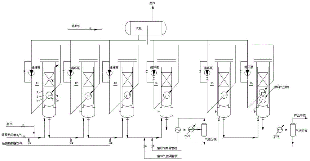
[0040] Specifically, if the non-circulation methanation system in this embodiment is used to produce methane, its detailed process is as follows:

[0041] Process gas flow:

[0042] Raw material rich in H 2 The gas is mixed with a small amount of CO-enriched gas and an appropriate amount of steam, enters the primary reactor R1 from the bottom, and flows upward along the gap airflow channel to reach the top of the reactor inner cylinder. In the interstitial gas flow channel, the synthesis gas and the inner cylinder of the reactor and the water-cooled tube perform combined heat exchange of gas and water, so that the synthesis gas can enter the catalyst bed from the top or side wall of the inner cylinder of the reactor at a relatively constant temperature. A catalytic reaction occurs, and after the reaction, a product gas of about 700°C (less than 800°C) is generated and enters the lower heat exchange section of the reactor. After heat exchange with boiler water, the temperature...


PUM


Abstract

The invention discloses a circulation-free methanation system which comprises a gas distribution methanation stage and a supplementation methanation stage, wherein in the gas distribution methanation stage, 1 to 3 stages of serially connected high-temperature reactors are adopted; in the supplementation methanation stage, 2 to 3 stages of serially connected low and medium-temperature reactors are adopted; the final-stage reactor in the gas distribution methanation stage is connected in series with the head-stage reactor in the supplementation methanation stage; technical gas discharged by the former stage of the reactor is used as part of or all the synthesized gas of the next stage of the reactor; technical gas discharged by the final-stage reactor is subjected to cooling separation to obtain a final methane product. The technical system is simple, and the reaction is steady, safe and reliable; the running cost and the manufacturing cost are low.

Description

technical field [0001] The invention relates to methanation reaction technology, in particular to a cycle-free methanation system. Background technique [0002] The methanation reaction is CO, CO 2 and H 2 A strong exothermic reaction at a certain temperature (a strong exothermic reaction usually refers to a reaction with an enthalpy greater than 200kJ / mol), under the usual synthesis gas composition, each percent of CO methanation can produce 74 ° C adiabatic Temperature rise, per percent CO 2 Methanation can produce an adiabatic temperature rise of 60°C. Limited by the operating temperature range of the catalyst, the current industrial methanation generally has a temperature resistance of 650-750°C. Therefore, how to effectively control the reaction exotherm and quickly remove heat to maintain the normal operation of the reaction is the focus of large-scale methanation process research and development. At present, most methanation units at home and abroad use a cyclic ...

Claims


Application Information

Patent Timeline
Patent Type & Authority Patents(China)
IPC IPC(8): C10L3/08
Inventor 汪勤亚刘廷斌王志远周焕文王正忠杨利国牛玉梅赵正绪彭良华兰玉顺李会张欢迎陈兆文杨洪文戴伟曹立军
Owner BEIJING HUAFU ENG
Why Eureka
Try Eureka