Processing method and boring clamp of front axle shell for excavator

A processing method and technology of excavators, which are applied in the direction of manufacturing tools, metal processing equipment, metal processing machinery parts, etc., can solve the problems of easy generation of waste, low processing efficiency, and troublesome clamping, so as to ensure processing accuracy and improve work efficiency. , Fast clamping and positioning effect

Active Publication Date: 2012-08-22
GUIZHOU JONYANG KINETICS
View PDF5 Cites 9 Cited by
  • Summary
  • Abstract
  • Description
  • Claims
  • Application Information

AI Technical Summary

Problems solved by technology

[0002] At present, the front axle housing is an important part of the high-speed excavator. The axis lines of the shaft holes at both ends of the excavator front axle housing must be on the same axis line, and the axis line should be on the same axis line as the excavator front axle. The end faces of the large holes on the shell are parallel. The existing processing method is to directly process the parts with a lathe. However, due to the complex structure of the part, it is very troublesome to use a lathe to process and clamp, and the processed product cannot guarantee the axis of the shaft holes at both ends. On the same axis line, it cannot be guaranteed that the axis line is parallel to the end face of the large hole on the front axle housing of the excavator. Therefore, the existing method has processing difficulties, low processing efficiency, and difficult quality assurance. It is easy to produce problems such as waste products, which has caused certain losses to the economy of the enterprise.
Therefore, the existing method of processing the front axle housing of the excavator is still not perfect

Method used


Image

  • Processing method and boring clamp of front axle shell for excavator
  • Processing method and boring clamp of front axle shell for excavator
  • Processing method and boring clamp of front axle shell for excavator

Examples


Embodiment Construction

[0018] The following describes the present invention in further detail with reference to the accompanying drawings and embodiments, but it is not intended to limit the present invention.

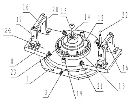
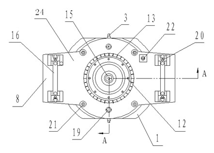
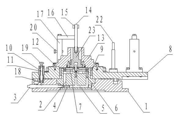
[0019] The embodiment of the present invention: a method for processing the front axle housing of an excavator. The front axle housing of the excavator is processed on an ordinary boring machine. First, a base with a horizontal reference surface is fixed on the worktable of the boring machine, and then the The end surface of the large hole on the front axle housing of the excavator is used as the positioning reference surface during processing. The end surface of the large hole on the front axle housing of the excavator used as the positioning reference surface is attached to the horizontal reference surface on the base, and then passed After the clamping device installed on the base clamps and fixes the front axle housing of the excavator, the shaft holes at both ends of the front axle housing ...


PUM


Abstract

The invention discloses a processing method of a front axle shell for an excavator. When the front axle shell of the excavator is processed on an ordinary boring machine, a base provided with a horizontal datum plane is fixedly arranged on a working platform of the boring machine first; afterwards, by utilizing the end surface of a big hole in the front axle shell of the excavator as a positioning datum plane in a processing process, the end surface of the big hole in the front axle shell of the excavator as the positioning datum plane is mounted on the horizontal datum plane on the base in an abutting way; afterwards, after the front axle shell of the excavator is clamped and fixed through a clamping device mounted on the base, axle holes at two ends of the front axle shell of the excavator can be processed through the ordinary boring machine; in such a way, the axial axes of the processed axle holes at the two ends of the front axle shell of the excavator can be enabled to be on the same axial axis parallel to the positioning datum planes of the axle holes; and compared with the prior art, the processing method not only has the advantages of simple structure and convenience in mounting, but also has the advantages of being ingenious in design and high in precision, being safe and reliable, being quick to clamp and position, being capable of guaranteeing the processing precision of the front axle shell, improving work efficiency, and the like.

Description

Technical field [0001] The invention provides a processing method and a boring fixture for a front axle housing of an excavator, which belong to the technical field of mechanical processing. Background technique [0002] At present, the front axle housing is an important part of the high-speed excavator. The axle center lines of the axle holes at both ends of the front axle housing of the excavator must be on the same axle center line, and the axle center line should be the same as the front axle of the excavator. The end faces of the large hole on the shell are parallel. The existing processing method is to use a lathe to directly process. However, due to the complex structure of the part, it is very troublesome to use the lathe to process the fashion clip, and the processed product cannot guarantee the axis line of the shaft hole at both ends On the same axis, it cannot be guaranteed that the axis is parallel to the end face of the large hole on the front axle housing of the ex...

Claims


Application Information

Patent Timeline
Patent Type & Authority Applications(China)
IPC IPC(8): B23B41/00B23Q3/00
Inventor 刘伟
Owner GUIZHOU JONYANG KINETICS
Why Eureka
Try Eureka