Spray cutter device

A technology of cutter and cutting surface, applied in the field of spray measurement, which can solve the problems of mutual interference of disturbance wave wavelengths, inability to accurately measure the wavelength and amplitude of disturbance waves, and interference of experimental results.

Active Publication Date: 2012-08-22
NAT UNIV OF DEFENSE TECH
View PDF5 Cites 1 Cited by
  • Summary
  • Abstract
  • Description
  • Claims
  • Application Information

AI Technical Summary

Problems solved by technology

[0005] The object of the present invention is to provide a spray cutter device to solve the problem that when the rotating 360° conical liquid film is photographed, the disturbance wave wavelengths on the liquid film surfaces on the two opposite sides interfere with each other, and the disturbance wave cannot be accurately measured from the picture. Wavelength and amplitude, technical issues that interfere with experimental results

Method used


Image

  • Spray cutter device
  • Spray cutter device
  • Spray cutter device

Examples


Embodiment Construction

[0023] The embodiments of the present invention will be described in detail below with reference to the accompanying drawings, but the present invention can be implemented in many different ways defined and covered by the claims.

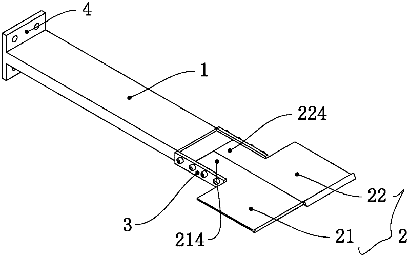
[0024] see figure 1 , a preferred embodiment of the present invention provides a spray cutter device, which is used to cut the conical liquid film rotated into 360° in half to form a liquid film without interference before and after. The spray cutter device includes a bracket 1, Cutter 2 and two connecting blocks 3 connecting the bracket 1 and the cutter 2.

[0025] The support 1 is a long rod, and the first end of the support 1 is connected to the baffle plate 4, and the baffle plate 4 has a plurality of threaded holes, which are connected with other parts by bolts, so that the spray cutter device of the present invention can be fixed.

[0026] The cutter 2 is installed on the upper surface of the second end opposite to the first end of the suppor...


PUM


Abstract

The invention provides a spray cutter device, which comprises a bracket and a cutter arranged on the bracket; the cutter comprises a first cutter and a second cutter which are arranged in parallel; the first cutter comprises a first cutting surface; the second cutter comprises a second cutting surface; both the first cutting surface and the second cutting surface are inclined surfaces; and the inclined directions of the first cutting surface and the second cutting surface are opposite; the first cutting surface and a vertical surface form a first included angle; the second cutting surface and the vertical surface form a second included angle; and the angle value of the first included angle is equal to that of the second included angle. The spray cutter device provided by the invention can incise a taper-shaped liquid film which is rotated in 360 degrees, so as to form liquid films that are not interfered with from front to back; and moreover, the experiment result is not interfered with when photographic processing is carried out for the liquid films.

Description

technical field [0001] The invention relates to the field of spray measurement, in particular to a spray cutter device. Background technique [0002] The research on primary atomization of liquid film belongs to the category of atomization mechanism research, and the commonly used methods include shadow method, laser holography method and backlight method. The shadow method reflects the change of the density gradient of the flow field, and can display the boundary information of the liquid film, but cannot capture the breaking process of the liquid film; the laser holography method can reproduce the three-dimensional structure of the liquid film, but the equipment is complicated and the cost is high; the backlight method has simple equipment, It is easy to operate and is one of the methods often used in the study of atomization mechanism. In the backlight method, a high-intensity light source is usually placed on the side opposite to the camera, and the liquid film structur...

Claims


Application Information

Patent Timeline
Patent Type & Authority Applications(China)
IPC IPC(8): B26D1/00
Inventor 刘娟王振国李清廉康忠涛
Owner NAT UNIV OF DEFENSE TECH
Why Eureka
Try Eureka