Gravure coating apparatus

A coating and gravure technology, which is applied in the device, coating, printing and other directions of coating liquid on the surface, can solve the problem of separation, bubbles K easily flow into the ink storage part, and the coating efficiency of the coating liquid inevitably deteriorates gradually. and other problems, to achieve the effect of improving the coating

Active Publication Date: 2012-08-22
FUJI KIKAI IND
View PDF8 Cites 11 Cited by
  • Summary
  • Abstract
  • Description
  • Claims
  • Application Information

AI Technical Summary

Problems solved by technology

In this way, when the air bubbles on the gravure roll 2 are replaced with the coating liquid at the installation portion of the above-mentioned doctor blade 35, it is easy to become a dense state of air bubbles near the installation portion of the above-mentioned doctor blade 35, which is unavoidable. When the coating efficiency of the coating liquid with respect to the gravure roll 2 gradually deteriorates
[0007] Additionally, if Figure 10 As shown, by setting the ink rectifying plate 36 installed in the ink storage part of the closed chamber in a state inclined to the direction along the gravure roll 2 (printing plate main body), the ink remaining on the gravure roll is removed through this part. 2 and the air attached to the peripheral surface of the gravure roller 2, the air bubbles K formed by the air flow along the wall surface of the above-mentioned ink rectifying plate 36 and are easily attached to the surface of the gravure roller 2 again. On the peripheral surface of the gravure roller 2, and with the rotation of the gravure roller 2, the front end portion of the ink rectifying plate 36 is easily separated from the peripheral surface of the gravure roller 2, so that the above-mentioned air bubbles K easily flow into the downstream chamber of the ink reservoir.

Method used


Image

  • Gravure coating apparatus
  • Gravure coating apparatus
  • Gravure coating apparatus

Examples


Embodiment Construction

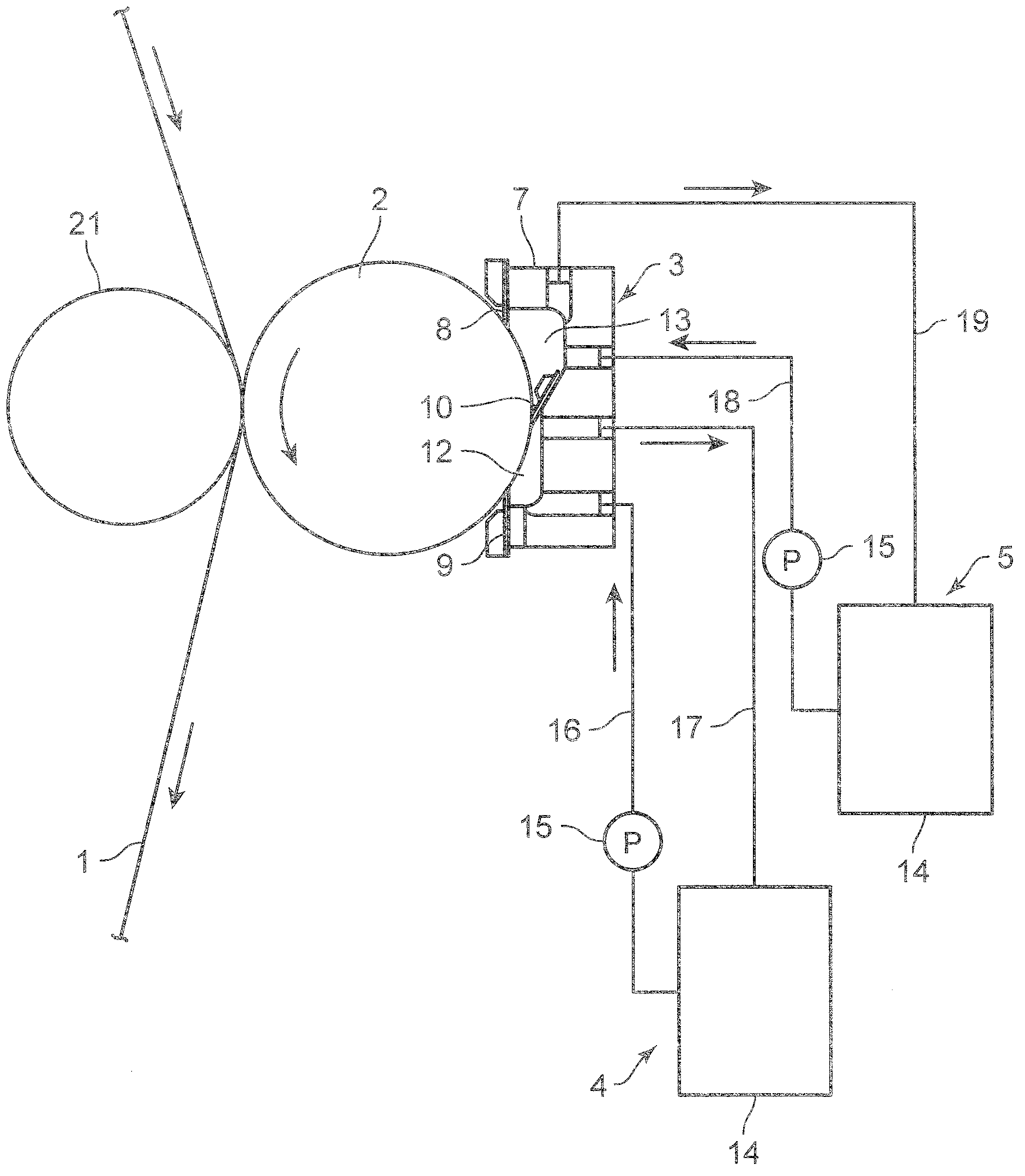
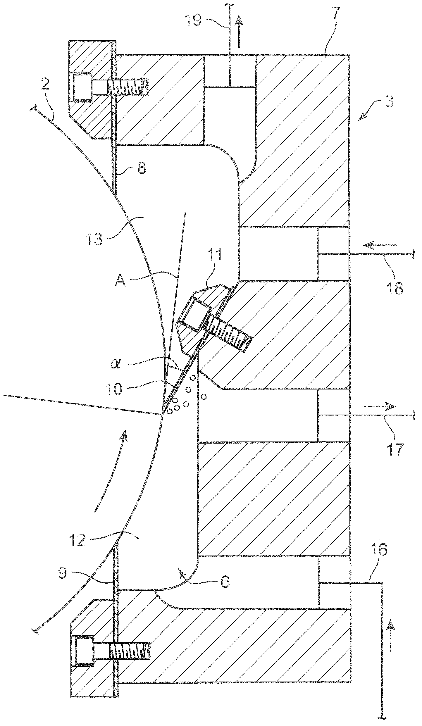
[0044] figure 1 and figure 2 The first embodiment of the gravure coating apparatus of the present invention is shown. This gravure coating device is a device for applying a coating liquid to a sheet-shaped base material 1, and includes a gravure roll arranged on a transport path of the base material 1 to transfer the coating liquid onto the surface of the base material 1. 2; a coating unit 3 for applying a coating liquid to the gravure roll 2 ; and first and second coating liquid supply mechanisms 4 and 5 for supplying the coating liquid to the coating unit 3 .

[0045] The substrate 1 is introduced between the above-mentioned gravure roll 2 and the support roll 21 disposed opposite thereto, the base material 1 is conveyed from above to below, and the above-mentioned gravure roll 2 is rotationally driven in a direction opposite to the conveyance direction of the substrate 1 , and at the same time, the gravure roll 2 is brought into contact with the substrate 1 to apply the...


PUM


Abstract

The invention provides a gravure coating apparatus which makes the air attached to a gravure roller properly displace with the coating liquid in a sealed cavity so that the coating property of the coating liquid relative to the gravure roller is effectively improved. The gravure coating apparatus comprises: a gravure roller (2) which transfers the coating liquid for the base material, a coating unit (3) which has a sealed cavity (7) for coating the coating liquid for the gravure roller, and a coating liquid feed mechanism (4, 5) which supplies the coating liquid to the coating liquid storage part (6) of the sealed cavity (7), wherein in the sealed cavity, the side part of the lower stream in the rotation direction of the gravure roller is sealed, and the redundant coating liquid attached to the gravure roller is removed by a knife coating blade (8); a sealed plate (9) is used for sealing the side part of the upper stream in the rotation direction of the gravure roller of the coating liquid storage part (6); and an internal component (10) is arranged between the sealed plate (9) and the knife coating blade (8), and is set to be that the front end part is propped to the periphery of the gravure roller (2) all along.

Description

technical field [0001] The present invention relates to a gravure coating device comprising: a gravure roll for transferring a coating liquid to the surface of a substrate; a coating unit having a closed chamber for applying the coating liquid to the gravure roll; A coating liquid supply mechanism for supplying coating liquid in the coating liquid reservoir formed in the chamber. Background technique [0002] Conventionally, as shown in Japanese Patent Application Laid-Open No. 2001-104851, the base material (to-be-coated body) to which the coating liquid has been transferred is pressure-contacted to the gravure roll by the back-up roll, and the coating liquid on the gravure roll is at the same time In the coating device for transfer to the object to be coated, there is a coating liquid storage part (shelter space) for storing the coating liquid coated on the gravure roll, and a weir plate is provided in the shielding space to form a In the filling part where the coating li...

Claims


Application Information

Patent Timeline
Patent Type & Authority Applications(China)
IPC IPC(8): B41F31/08
CPCB05C1/0808B05C1/12B05C11/04B05C19/06B41F31/07
Inventor 森川亮中岛裕之矶崎彻安田芳章
Owner FUJI KIKAI IND
Why Eureka
Try Eureka