Blade load reduction for wind turbine

A technology of wind turbines and turbines, applied in the field of load systems, which can solve the problems of preventing corrective pitch action, hindering immediate identification, delay, etc.

Inactive Publication Date: 2012-08-22
SSB WIND SYST
View PDF14 Cites 13 Cited by
  • Summary
  • Abstract
  • Description
  • Claims
  • Application Information

AI Technical Summary

Problems solved by technology

This free component prevents the immediate identification of the onset of gyration-induced l...

Method used


Image

  • Blade load reduction for wind turbine
  • Blade load reduction for wind turbine
  • Blade load reduction for wind turbine

Examples


Embodiment Construction

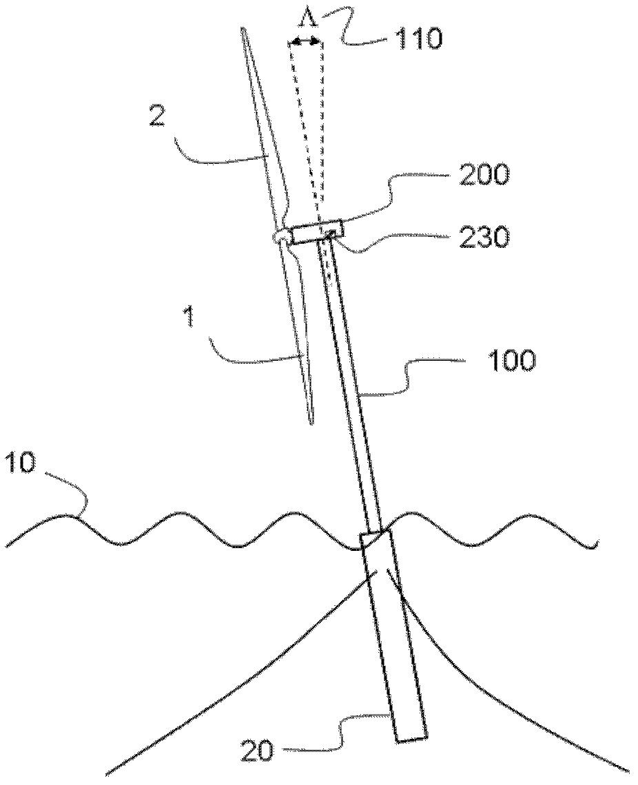
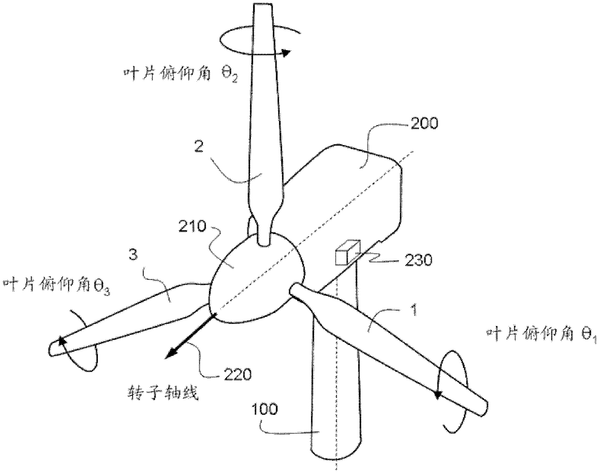
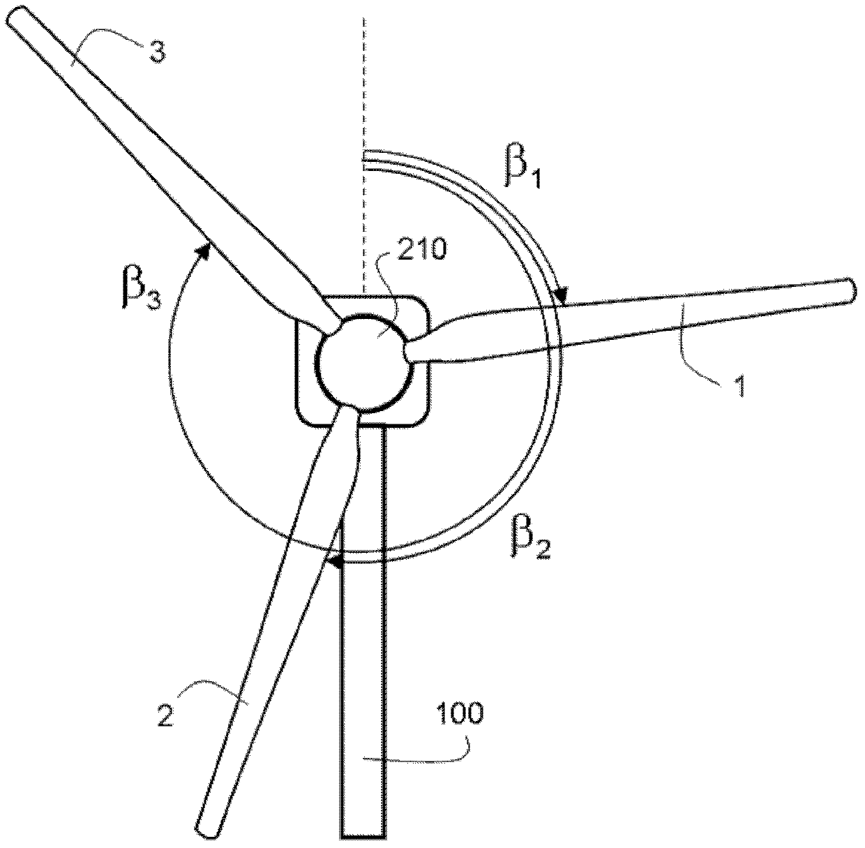
[0028] wind turbines include figure 1 and 2 Two or more blades 1 , 2 and 3 are attached to a hub 210 that rotates about an axis of rotation 220 relative to the nacelle 200 . Here, the rotational speed of the hub 210 is indicated by the letter Ω. Apart from this rotational degree of freedom, the hub is fixedly attached to the nacelle. Within the hub, each blade has a pitch change mechanism to change the angle of attack of the blade. Blade pitch mechanisms are well known in the art and are not shown in the drawings. In addition to the blade pitch degree of freedom, each blade is fixedly attached to the hub by a bearing unit. This type of rotor is called a "rigid rotor". The nacelle is supported by a tower 100 . The invention described here can be applied to both onshore and offshore wind turbine sites. exist figure 1 In , the wind turbine is shown supported by a floating structure 20 on the sea 10, which itself is attached to the seabed using cables.

[0029] sea ​​pitc...


PUM


Abstract

A wind turbine having a hub (210) rotably attached to a nacelle (200), at least two blades (1, 2, 3) rotationally attach to the hub (210) to allow a change in blade pitch angle ( 1 , 2 3 ) a blade-pitch system (250) for individually controlling the blade-pitch angle ( 1 , 2 3 ) of each blade, a supervisory control unit for issuing a first pitching command, a rotor position sensor (238) generating a rotor-position signal () indicative of the rotor azimuthally position, a rotor-rotational-rate sensor (236) generating a rotor-rotational-rate signal ( CR ) indicative of the rotor rotational speed, and a tower (100) supporting the nacelle (200), comprising a nautical-pitch-rate sensor (230) generating a nautical-pitch-rate signal ( ) indicative of the nautical-pitch-rate of the wind turbine and a computational unit (240, 241) receiving turbine-state signals comprising the rotor-position signal (), the rotor-rotational-rate signal ( CR ), and the nautical-pitch-rate signal ( ).

Description

technical field [0001] The present invention relates to wind turbines with variable pitch blades and to a system for configuring blade pitch commands based on signals indicative of wind turbine status to reduce loads on wind turbine components. Background technique [0002] The increase in mean wind speed with height above the ground has led to the use of very tall towers, for example, 60 to 120 meters, to support the nacelle and rotor of the wind turbine. In order to extract energy from the wind, the wind turbine rotor must decelerate the wind, thus placing large thrust loads on the tower. Tall towers and large unstable loads caused by gusts and eddies in high winds can potentially produce large tower top motions and tower swings. [0003] Various ideas have been proposed to use the aerodynamic forces on the rotor blades to attenuate tower oscillations in the direction of the rotor axis. [0004] US 4,420,692 describes a system that uses accelerometer signals indicative o...

Claims


Application Information

Patent Timeline
IPC IPC(8): F03D7/00
CPCF03D7/0224F05B2200/11F05B2200/262F05B2240/93F05B2240/95F05B2260/96F05B2270/1095F05B2270/304F05B2270/309F05B2270/328F05B2270/331F05B2270/708F03D13/25Y02E10/727Y02E10/72
Inventor F.伯托洛蒂
Owner SSB WIND SYST
Why Eureka
Try Eureka