
Soil mass elastic wave velocity testing piezoelectric sensor for centrifugal model test

A centrifugal model test, electrical sensor technology, applied in the direction of instruments, measuring devices, measuring propagation speed, etc., can solve the problem of testing sensors without shear waves and compression waves, and achieve the effect of reducing the impact and ensuring the effect of compression vibration

Inactive Publication Date: 2012-08-22
ZHEJIANG UNIV
View PDF4 Cites 7 Cited by
  • Summary
  • Abstract
  • Description
  • Claims
  • Application Information

AI Technical Summary

Problems solved by technology

However, there is currently no compression wave velocity test method and corresponding sensor for centrifugal model tests, and there is no joint test sensor for shear wave and compression wave.

Method used


Image

  • Soil mass elastic wave velocity testing piezoelectric sensor for centrifugal model test
  • Soil mass elastic wave velocity testing piezoelectric sensor for centrifugal model test
  • Soil mass elastic wave velocity testing piezoelectric sensor for centrifugal model test

Examples


Embodiment Construction

[0018] Below in conjunction with accompanying drawing and embodiment the present invention is described in further detail:

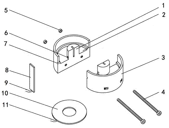
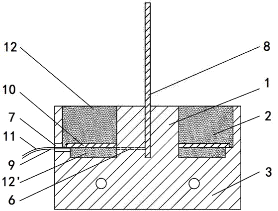
[0019] Such as figure 1 , figure 2 As shown, the example of the present invention is mainly composed of a cylindrical plexiglass base 3, a base connecting screw 4, a base connecting nut 5, a rectangular piezoelectric ceramic sheet 8, an annular piezoelectric ceramic sheet 10, glass glue 12 and 12'. The cylindrical insulating base 3 is connected by two semi-cylindrical insulating bases through base connecting screws 4 and base connecting nuts 5 . The upper half of the cylindrical insulating base 3 is provided with a circular stepped hole 2, and the center of the circular stepped hole 2 forms a cylindrical core seat 1, and the cylindrical core seat 1 is radially provided with a rectangular groove, and the rectangular piezoelectric ceramic sheet 8 is embedded in a rectangular groove, the rectangular piezoelectric ceramic sheet 8 extends out of the cylind...


PUM


Abstract

The invention discloses a soil mass elastic wave velocity testing piezoelectric sensor for centrifugal model test. The sensor is formed by connecting two semi-cylindrical insulating bases into a cylindrical insulating base, wherein a circular ring stepped bore is arranged at the upper half of the insulating base, a cylindrical core seat which is radially provided with a rectangular groove is arranged in the center, a rectangular piezoelectric ceramic plate is embedded into the rectangular groove and extends out of the insulating base, a ring piezoelectric ceramic plate is sleeved outside the cylindrical core seat and is placed on the ledge of the circular ring stepped bore of the insulating base, glass cement is fully filled in the cavity of the insulating base, and the leads of both the rectangular piezoelectric ceramic plate and the ring piezoelectric ceramic plate are led out from the hole of the cylindrical surface of the insulating base. The soil mass elastic wave velocity testing piezoelectric sensor for centrifugal model test has smaller dimensions and less influences to a model soil mass during the centrifugal model test; the lower end of the rectangular piezoelectric ceramic plate is fixed by the cylindrical core seat to form a cantilever structure, the ring piezoelectric ceramic plate is fixed outside the cylindrical core seat, so the signal quality of shear and compressional waves is ensured; and the soil mass elastic wave velocity testing piezoelectric sensor for centrifugal model test has the function of simultaneously testing the shear and compressional waves.

Description

technical field [0001] The invention relates to a sensor for wave velocity testing, in particular to a piezoelectric sensor for testing soil elastic wave velocity for centrifugal model tests. Background technique [0002] Elastic wave velocity is an important parameter reflecting the characteristics of the site or model soil, mainly including shear wave velocity and compression wave velocity. At present, the main methods of on-site shear wave and compression wave velocity testing include the cross-hole method and the surface wave method, and all of them have been successfully applied to the actual site wave velocity testing. [0003] The centrifugal model test requires that the sensor should have the characteristics of small size and high sensitivity. Commonly used on-site test equipment and sensors are large in size and complicated in operation, so they cannot be applied in scale model tests. In the centrifugal model test, the piezoelectric ceramic sensor is generally use...

Claims


Application Information

Patent Timeline
IPC IPC(8): G01H5/00
Inventor 周燕国孙政波陈云敏凌道盛黄博李永刚黄锦舒
Owner ZHEJIANG UNIV
Learn More