Automatic graphing method for geological section map of non-isobathic drilled hole

A technology for geological profile and automatic mapping, applied in special data processing applications, instruments, electrical digital data processing, etc. question

Inactive Publication Date: 2012-08-22
SHANGHAI TONGYAN CIVIL ENGINEERING TECHNOLOGY CORP LTD +1
View PDF2 Cites 15 Cited by
  • Summary
  • Abstract
  • Description
  • Claims
  • Application Information

AI Technical Summary

Benefits of technology

The technical effect of this patented technology allows for efficient processing of complicated layers by utilizing measurements from different types of holes that are difficult or expensive to measure accurately due to their complexity. This results in automatic mapping of these structures on an image plane during drilling operations.

Problems solved by technology

This patented describes two technical problem: current manual techniques used during automated drawings cannot efficiently handle complicated scenarios like faults or incomplete drilling due to changes overtime caused by previous analysis results.

Method used


Image

  • Automatic graphing method for geological section map of non-isobathic drilled hole
  • Automatic graphing method for geological section map of non-isobathic drilled hole

Examples


Embodiment

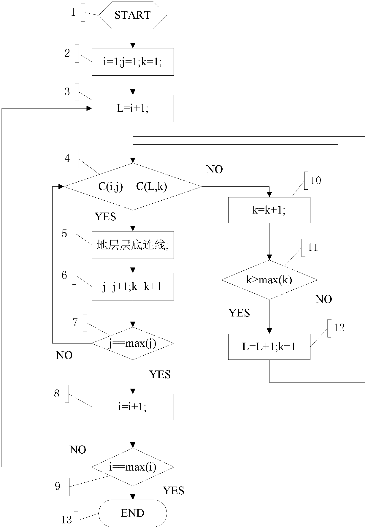
[0028] A method for automatically forming a geological profile of a non-contour borehole, comprising the following steps:

[0029] Step 1: Standardize the stratum information of each borehole, unify the stratum code, and establish a list of boreholes and strata of boreholes, make preparations, and then perform step 2;

[0030] Step 2: The stratigraphic connection lines of the geological section map are processed in order from left to right and from top to bottom, and the stratigraphic connection is performed, and i, j, and k are all assigned 1, and step 3 is performed.

[0031] Step 3: assign i+1 to L, and execute step 4;

[0032] Step 4: Judging whether C(i, j) and C(L, k) are the same, where C(i, j) represents the standard stratigraphic code of the jth stratum in borehole i, if they are the same, go to step 5, otherwise go to step 10;

[0033] Step 5: For the bottom connection of the formation, perform step 6;

[0034] Step 6: assign j+1 to j, k+1 to k, and execute step 7...


PUM

PropertyMeasurementUnit
Thicknessaaaaaaaaaa

Abstract

The invention relates to an automatic graphing method for a geological section map of a non-isobathic drilled hole. The automatic graphing method is characterized by comprising the following steps of: 1) standardizing stratum information of each drilled hole, unifying stratum numbers, and generating a drilled hole list and a drilled hole stratum list; 2) carrying out stratum wire connection from left to right and from top to bottom; and 3) filling stratum figure patterns on the geological section map after the wire connection, and processing the patterns. Compared with the prior art, the automatic graphing method provided by the invention can effectively process various complex stratums, particularly the geological section map can be automatically graphed by using drilled hole stratum data of the non-isobathic drilled holes of various projects.

Description


Claims


Application Information

Patent Timeline
Owner SHANGHAI TONGYAN CIVIL ENGINEERING TECHNOLOGY CORP LTD
Why Eureka
Try Eureka