Pressure filter device

A filter device and pressure technology, applied in the direction of filter circuit, filter separation, membrane filter, etc., can solve the problem of time-consuming decomposition, and achieve the effect of cost saving

Inactive Publication Date: 2012-08-22
FILTRATION GRP GMBH
View PDF6 Cites 2 Cited by
  • Summary
  • Abstract
  • Description
  • Claims
  • Application Information

AI Technical Summary

Problems solved by technology

However, a disadvantage of the known ventilation line is that when changing the filter element, due to its configuration on the filter housing cover, said ventilation line first has to be disassembled with time-consuming and subsequently reassembled

Method used


Image

  • Pressure filter device
  • Pressure filter device
  • Pressure filter device

Examples


Embodiment Construction

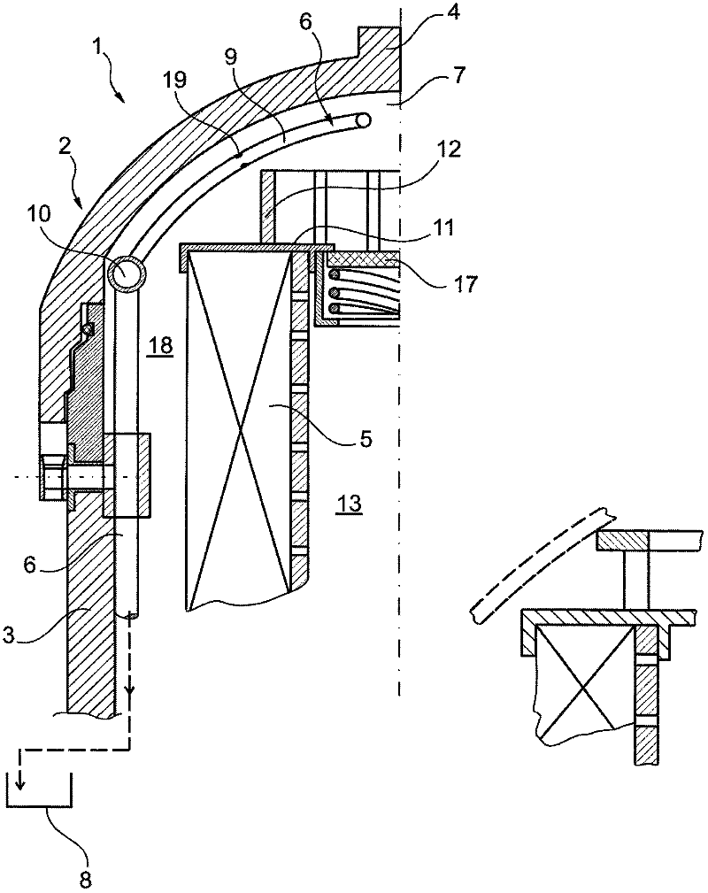
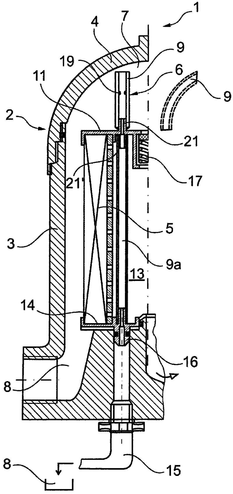
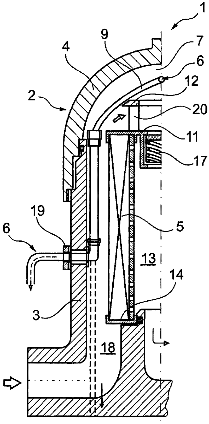
[0015] according to figure 1 , the pressure filter device 1 according to the invention is in particular configured as a hydraulic filter device and operates, for example, in a pressure range between approximately 16 and 20 bar, the pressure filter device 1 comprising a filter housing 2 which essentially consists of a filter housing tank 3 and a filter housing tank 3 and A rotatable filter housing cover 4 consists, in particular, of a rotatable filter housing cover 4 which can be connected to said filter housing pot 3 in a pressure-tight manner. in accordance with Figures 1 to 3 In the filter housing 2 , only the left half of which is shown in each case, a filter element 5 , in particular of the annular filter element type, is accommodated in the filter housing 2 . According to the present invention, in accordance with Figures 1 to 3 A ventilation line 6 is attached to the filter housing 3 of the pressure filter device 1 of the ® pressure filter device 1 , which connects th...


PUM


Abstract

The invention relates to a pressure filter device (1), especially a hydraulic filter device, comprising a filter housing (2) provided with a filter housing pot (3) and a filter housing cover (4) that can be connected in a pressure-tight manner to said pot, and at least one filter element (5) arranged in the filter housing (2). According to the invention, a vent line (6) fixed to the filter housing pot (3) connects a dirty-side gas collection region (7) located directly beneath the filter housing cover (4) to a (hydraulic liquid) tank (8), or a vent line (6) fixed to the filter element (5) and guided through an upper end disk (11) of same connects a dirty-side gas collection region (7) located directly beneath the filter housing cover (4) to a (hydraulic liquid) tank (8) via a clean side (13) of the filter element (5).

Description

technical field [0001] The invention relates to a pressure filter device, in particular to a hydraulic filter device according to the preamble of claim 1 . Background technique [0002] In known pressure filter devices, this is often the case, in the filter housing of which the air is separated while collecting directly below the filter housing cover. If the air is not expelled, it grows in volume thereby reducing the available filter space for the liquid being filtered. Therefore, if the air collected, for example in the filter element placed upright, is not expelled, no air flow can pass through an area which expands continuously from the top, and the filter cannot therefore be used. In addition, in the case of a bypass, it may occur that an air flow, in particular in the case of a bypass, provides an insufficient amount of oil to the system, and may thus lead to damage to the shaft. In particular in open systems, a large amount of air is introduced and divided, for exam...

Claims


Application Information

Patent Timeline
Patent Type & Authority Applications(China)
IPC IPC(8): B01D29/21B01D36/00
CPCB01D29/21B01D36/001B01D2201/291B01D2201/316B01D2201/4023B01D2201/4046B01D2201/4084
Inventor 阿尔贝特·希克
Owner FILTRATION GRP GMBH
Why Eureka
Try Eureka