Liquid crystal suction device and liquid crystal coating equipment

A suction device and liquid crystal technology, applied in the field of liquid crystal, to achieve the effect of consistent weight

Inactive Publication Date: 2012-08-29
TCL CHINA STAR OPTOELECTRONICS TECH CO LTD
View PDF4 Cites 5 Cited by
  • Summary
  • Abstract
  • Description
  • Claims
  • Application Information

AI Technical Summary

Problems solved by technology

However, the currently used liquid crystal pipeline will still draw air in the liquid crystal container

Method used


Image

  • Liquid crystal suction device and liquid crystal coating equipment
  • Liquid crystal suction device and liquid crystal coating equipment
  • Liquid crystal suction device and liquid crystal coating equipment

Examples


Embodiment Construction

[0032] The present invention will be described in detail below in conjunction with the accompanying drawings and embodiments.

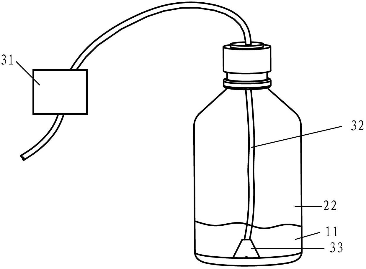
[0033] refer to image 3 , image 3 It is a structural diagram of the first embodiment of the liquid crystal suction device of the present invention. The liquid crystal suction device of this embodiment includes: a first vacuum generating unit 31 , a flexible suction tube 32 and a load body 33 . Wherein, the load body 33 is arranged on one end of the flexible suction pipe 32 , and the other end of the flexible suction pipe 32 is connected to the first vacuum generating unit 31 .

[0034] refer to Figure 4 with Figure 5 , Figure 4 It is an enlarged schematic diagram of the load body 33 in the first embodiment of the liquid crystal absorption device of the present invention, Figure 5 yes Figure 4 The three-dimensional schematic diagram of the load body in . As shown in the figure, the structure of the load body 33 is conical, truncated cone ...


PUM


Abstract

The invention discloses a liquid crystal suction device. The device comprises a first vacuum generating unit, a flexible suction pipe and a load body, wherein the load body is arranged at one end of the flexible suction pipe; and the other end of the flexible suction pipe is connected with the first vacuum generating unit. The invention further discloses liquid crystal coating equipment. In this way, the invention can ensure that the suction end of a liquid crystal pipeline is kept below the liquid crystal level all the time so as to prevent the suction end of the liquid crystal pipeline from sucking air bubbles.

Description

technical field [0001] The invention relates to the technical field of liquid crystals, in particular to a liquid crystal absorption device and liquid crystal coating equipment. Background technique [0002] A liquid crystal display device (LCD) includes a thin film transistor (TFT) array substrate, a color filter array substrate, and a liquid crystal layer sandwiched therebetween. A liquid crystal display device (LCD) produces an image by controlling a voltage applied to a liquid crystal layer within each pixel and thereby allowing light to transmit in varying amounts. [0003] The formation of the liquid crystal layer is mostly achieved by liquid crystal coating. Liquid crystal coating is to apply a certain amount of liquid crystal to each panel area defined on a (TFT) array substrate or a color filter array substrate in the form of a plurality of liquid crystal droplets corresponding to a reference amount of liquid crystal. Usually, a liquid crystal dropping machine is ...

Claims


Application Information

Patent Timeline
Patent Type & Authority Applications(China)
IPC IPC(8): G02F1/1341B05C11/10
CPCB29D11/00788G02F1/1341G02F1/13415
Inventor 蔡文卿
Owner TCL CHINA STAR OPTOELECTRONICS TECH CO LTD
Why Eureka
Try Eureka