Pipeline monitoring system

A monitoring system and pipeline technology, applied in the direction of comprehensive factory control, comprehensive factory control, electrical program control, etc., can solve problems such as wasting inspection time, and achieve the effects of reducing maintenance costs, reducing disaster expansion, and reducing losses

Inactive Publication Date: 2012-08-29
KUN SHAN UNIVERSITY
View PDF7 Cites 3 Cited by
  • Summary
  • Abstract
  • Description
  • Claims
  • Application Information

AI Technical Summary

Problems solved by technology

[0005] The purpose of the present invention is to provide a pipeline monitoring system to solve the problem that in the past, monitors can only inspect pipelines by visual inspection, which wastes a lot of inspection time

Method used


Image

  • Pipeline monitoring system
  • Pipeline monitoring system
  • Pipeline monitoring system

Examples


Embodiment Construction

[0050] In order to further explain the technical solution of the present invention, the present invention will be described in detail below through specific examples.

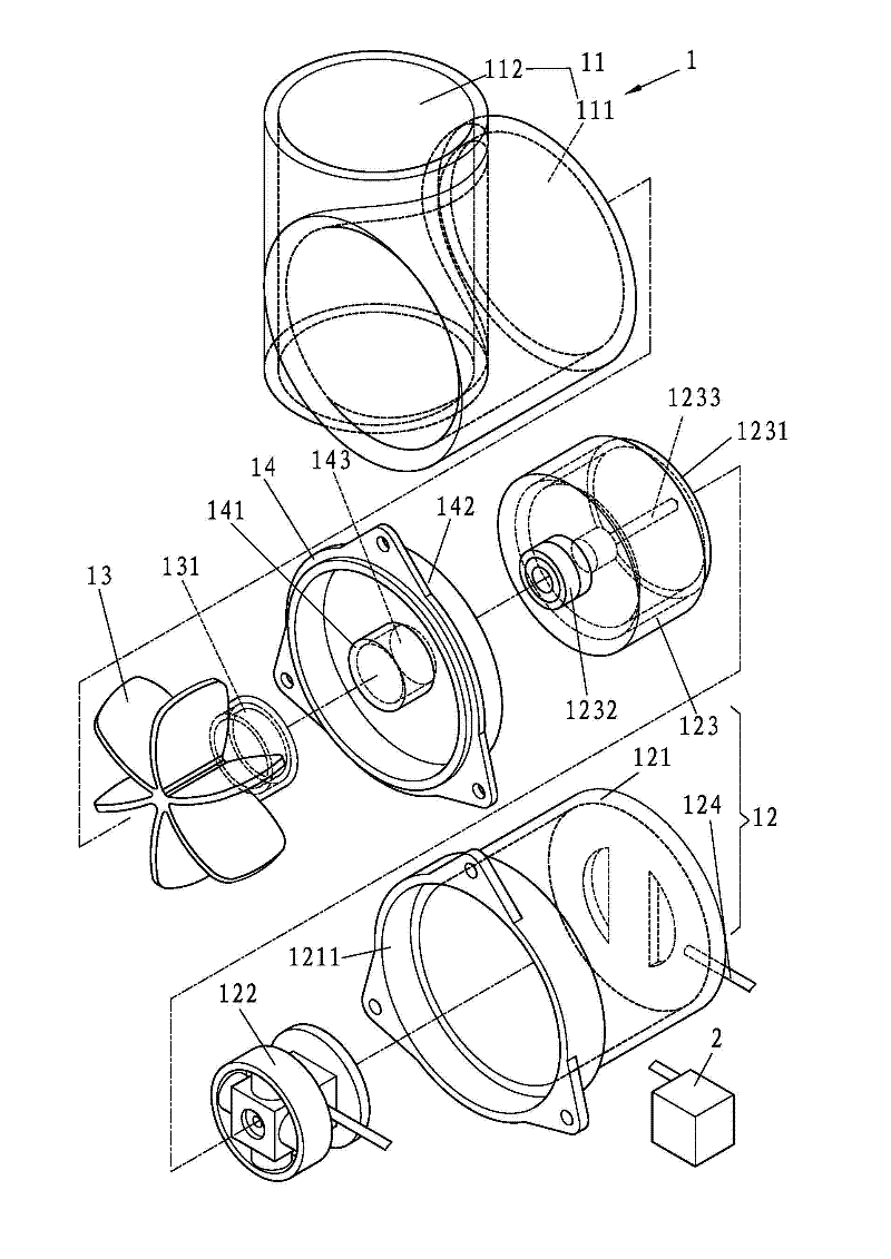
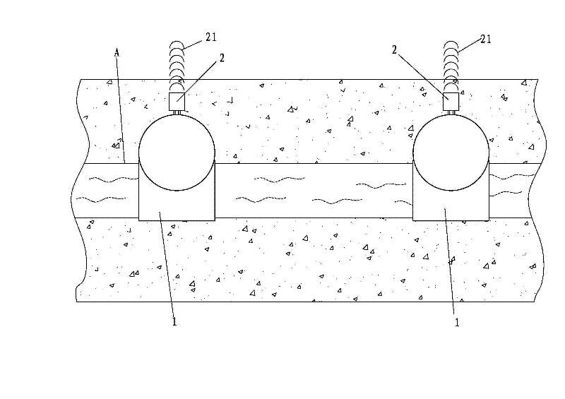
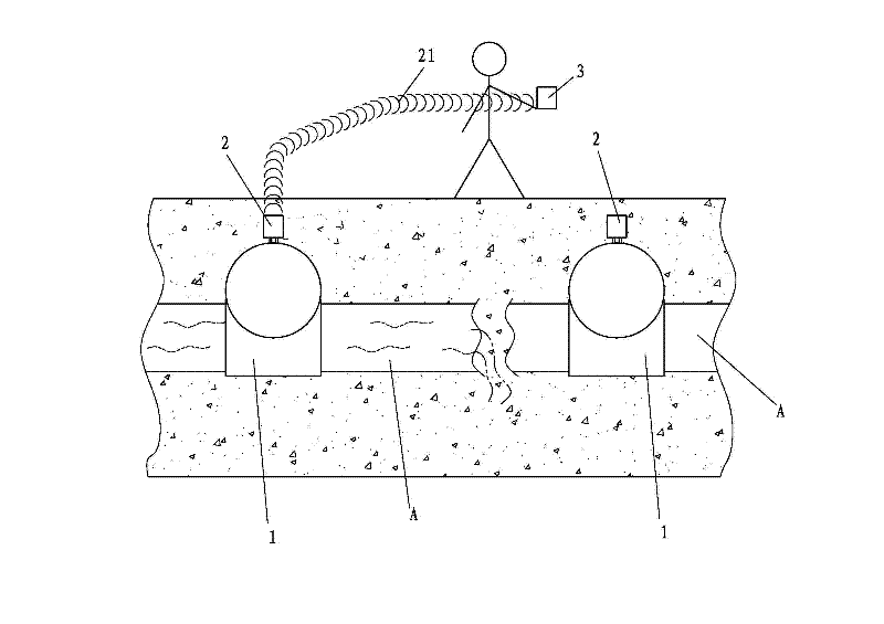
[0051] First, see figure 1 and figure 2 As shown, the present invention discloses a pipeline monitoring system, which is applied to a long-distance transmission pipeline A installed on the ground or underground, such as water pipes, oil pipes or gas pipelines, etc., including:

[0052] At least one tube current power generation device 1 is installed on the pipeline A. The aforementioned tube current power generation device 1 generates electric energy through the fluid flow in the pipeline A. It includes a shell base 11 and at least one power generation unit 12, wherein the shell base 11 is set There is a chamber 111 and a pipe body 112, and the pipe body 112 intersects with the chamber 111 eccentrically. The pipe body 112 communicates with the pipeline A, and the blade 13 with a magnetic ring 131 is arranged ...


PUM


Abstract

The invention discloses a pipeline monitoring system, which includes at least one pipe flow power generating device and at least one information device, wherein the pipe flow power generating device can generate power through flowing of a fluid in a pipeline, the power is supplied to the information device and further enables the information device to send out a signal, and a pipeline monitor judges whether the pipeline is broken or ruptured through the signal. Therefore, the pipeline monitoring system can achieve the purpose of rapidly detecting a pipeline or finding out a broken position of the pipeline.

Description

technical field [0001] The invention relates to a pipeline monitoring system, in particular to a monitoring system for judging whether the pipeline at the position of the signal is damaged or not and monitoring the flow of the pipeline through whether the signal is sent out. Background technique [0002] At present, fluids (such as tap water, oil or natural gas, etc.) that need to be transported over long distances are mostly transported through pipelines to reduce transportation costs. Man-made or natural disasters cause pipeline breakage or damage, resulting in fluid leakage and environmental pollution or hollowing out the ground and causing disasters such as subsidence. [0003] At this time, the length of time for pipeline monitors to find out the damage will affect the size of the entire disaster. In the past, pipeline monitors used visual inspection along the pipeline path to find the pipeline damage. But it takes a long time. If the pipeline is buried, it is even mor...

Claims


Application Information

Patent Timeline
Patent Type & Authority Applications(China)
IPC IPC(8): G05B19/418
CPCY02P90/02
Inventor 王松浩张培华王浩
Owner KUN SHAN UNIVERSITY
Why Eureka
Try Eureka