Eureka AIR delivers breakthrough ideas for toughest innovation challenges, trusted by R&D personnel around the world.

Labelling device

A labeling and labeling technology, applied in the direction of labeling, labels, labeling machines, etc.

Active Publication Date: 2012-09-05
KRONES AG
View PDF10 Cites 18 Cited by
  • Summary
  • Abstract
  • Description
  • Claims
  • Application Information

AI Technical Summary

Problems solved by technology

[0004] Another problem is the calibration of the unit after replacing parts

Method used


Image

  • Labelling device
  • Labelling device
  • Labelling device

Examples


Embodiment Construction

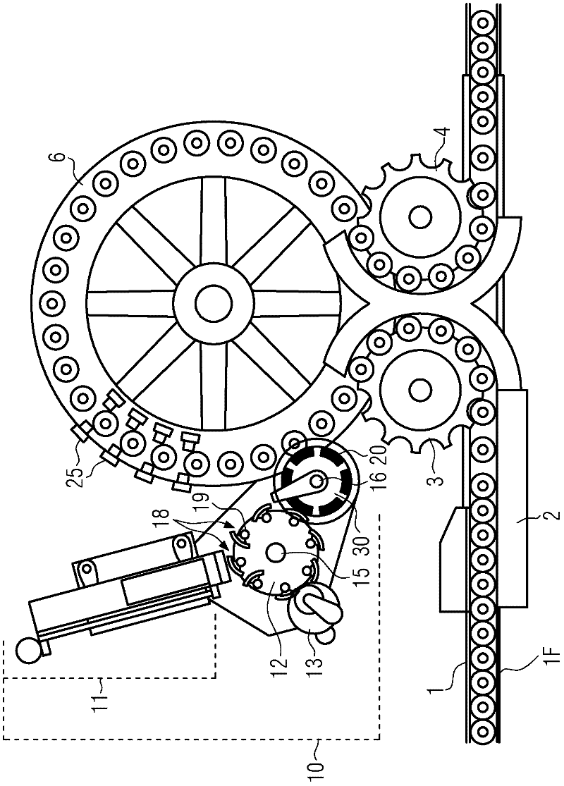
[0026] figure 1 Shown is a labeling device / labelling machine according to the invention, which has a feed unit 1 for conveying containers 1F to be labeled, which are distributed by means of a distribution unit 2, for example a distribution screw, and which are distributed by a star for sorting. The shape 3 is sorted on the feed table 6 which rotates clockwise in the drawing. After the container has essentially completely circled the feed table on its edge and has first been labeled there, the container 1F is sorted out of the feed table again by means of another star 4 and is continued to send. During the walk around the feed table, the containers are labeled by means of the labeling unit 10 and the labels are pressed by the pressing or pressing elements 25 .

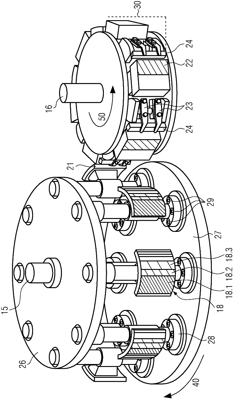
[0027] Here, the labeling unit 10, which is typically constructed on a base plate or chassis not shown here, comprises at least one label container or label magazine 11, a glue applicator with a gluing roller 13, a pa...


PUM


Abstract

The invention provides a labeling device with at least a labeling assembly used for labeling a container, the labeling assembly is provided with: a pallet rotor with at least a pallet shaft, which is provided with at least a pallet; at least a labeling container; a gripping cylinder with at least a gripper with one or more gripping fingers; wherein, the pallet is arranged at the pallet shaft in a displaceable manner such that a front edge of the pallet is aligned on an edge of a label in a labeling container with respect to a rotating direction of the rotor during taking of the label from the labeling container.

Description

technical field [0001] The invention relates to a labeling device according to the preamble of claim 1 and a method for labeling according to the preamble of claim 8 . Background technique [0002] Labeling machines and labeling devices for labeling containers, in particular bottles, are described in the prior art. [0003] DE 10 2006 062 511 A1 deals with the fact that labeling units, pallets, labels must be replaced or replenished each time on the labeling equipment when the label format changes, that is, when changing from one type of label to another. Container and grab rollers. The corresponding operations required for this are time-consuming and complex and mean that the labeling plant is frequently out of service for a considerable period of time. Furthermore, the storage, purchase and logistics of the parts are associated with relatively high outlay, for example different gripper rollers typically have to be provided for each label format. [0004] Another problem...

Claims


Application Information

Patent Timeline
IPC IPC(8): B65C9/16B65C9/08B65C3/16B65C9/06B65C9/10
CPCB65C9/16
Inventor 约瑟夫·马耶尔
Owner KRONES AG
Why Eureka
Eureka Blog
Learn More