
High-redundancy beam-string truss structure and implementation method

A string truss, high-redundancy technology, applied in building components, building structures, roofs, etc., can solve the problems of lower chord flexible cables occupying large indoor headroom, upper chord truss collapse, adjacent structure damage, etc., to achieve safety Improved performance, delayed collapse, reduced sag height effects

Inactive Publication Date: 2012-09-05
CIVIL AVIATION UNIV OF CHINA
View PDF3 Cites 17 Cited by
  • Summary
  • Abstract
  • Description
  • Claims
  • Application Information

AI Technical Summary

Problems solved by technology

[0006] Although the string truss structure has reasonable stress, high rigidity, and light weight, its application fields are limited because its lower string flexible cables need to occupy a large amount of indoor clearance
In addition, once the flexible cables of the traditional tension truss structure break, the upper chord truss will collapse and cause continuous damage to adjacent structures, resulting in catastrophic accidents

Method used


Image

  • High-redundancy beam-string truss structure and implementation method
  • High-redundancy beam-string truss structure and implementation method
  • High-redundancy beam-string truss structure and implementation method

Examples


Embodiment Construction

[0024] The high-redundancy string tension truss structure and implementation method provided by the present invention will be described in detail below in conjunction with the accompanying drawings and specific embodiments.

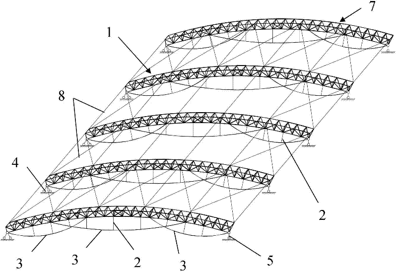
[0025] Such as figure 1 As shown, the high-redundancy chord truss structure provided by the present invention includes an upper chord truss 1, a plurality of struts 2, a plurality of stay cables 3, a fixed hinge support 4 and a sliding hinge support 5, wherein the upper chord truss 1 is composed of A plurality of upper chord truss members 6 are connected to each other by bolt balls or welded balls to form an upright triangular pyramidal space arch truss; the two ends of each stay cable 3 are connected to the two spherical nodes at the bottom of the upper chord truss 1 at a distance, and Partial structures of multiple stay cables 3 are arranged in a staggered manner; multiple struts 2 are vertically connected between the lower part of the upper chord truss...


PUM


Abstract

The invention relates to a high-redundancy beam-string truss structure and an implementation method. The high-redundancy beam-string truss structure comprises an upper string truss, a plurality of stay bars, a plurality of stay ropes, a fixed hinged support and a sliding hinged support, wherein the upper string truss is a positively arranged triangular cone space arch truss formed by mutually connecting a plurality of upper string truss rod pieces; two ends of each stay rope are connected with two spherical joints at the lower part of the upper string truss at an interval, and parts of the plurality of stay ropes are alternatively arranged; the plurality of stay bars are vertically connected among the lower part of the upper string truss and the plurality of stay ropes at intervals; the upper end of the fixed hinged support is connected with the spherical joint at the lower part of one side of the upper string truss, and the lower end of the fixed hinged support is arranged on a supporting structure on one side of the upper string truss in a fixing manner; and the upper end of the sliding hinged support is connected with another spherical joint at the lower part of the other side of the upper string truss, and the lower end of the sliding hinged support is arranged on a supporting structure at the other side of the upper string truss in a sliding manner. The high-redundancy beam-string truss structure and the implementation method have the advantages of high structure redundancy, good collapse resistance, simplicity and convenience in construction, excellent safety and the like.

Description

technical field [0001] The invention belongs to the technical field of large-span prestressed steel structures of building structures, and in particular relates to a high-redundancy tension string truss structure and an implementation method. Background technique [0002] The tension truss structure was first proposed by Professor M. Saitoh of Nihon University in 1986. This structure is a new type of hybrid roof system different from the traditional structure. The self-balancing hybrid structure composed of cables and intermediate compression struts is also a relatively successful long-span prestressed spatial structure in the development of hybrid structural systems. [0003] The string truss structure is characterized by a simple system, clear force, and various structural forms, giving full play to the advantages of rigid and flexible materials, and it is simple and convenient to manufacture, transport, and construct, so it has been well applied. In recent years, the lon...

Claims


Application Information

Patent Timeline
IPC IPC(8): E04B7/14E04G21/14
Inventor 刘国光武志玮谭振
Owner CIVIL AVIATION UNIV OF CHINA
Learn More