Eureka AIR delivers breakthrough ideas for toughest innovation challenges, trusted by R&D personnel around the world.

Transparent display device

A transparent display and transparent electrode technology, applied in static indicators, optics, instruments, etc., can solve the problems of reducing the transmittance of transparent display devices, and achieve the effect of changing, realizing grayscale, and improving transmittance

Active Publication Date: 2012-09-05
BOE TECH GRP CO LTD
View PDF5 Cites 9 Cited by
  • Summary
  • Abstract
  • Description
  • Claims
  • Application Information

AI Technical Summary

Problems solved by technology

The use of polarizers greatly reduces the transmittance of transparent display devices

Method used


Image

  • Transparent display device
  • Transparent display device
  • Transparent display device

Examples


Embodiment Construction

[0031] The following will clearly and completely describe the technical solutions in the embodiments of the present invention with reference to the accompanying drawings in the embodiments of the present invention. Obviously, the described embodiments are only some, not all, embodiments of the present invention. Based on the embodiments of the present invention, all other embodiments obtained by persons of ordinary skill in the art without creative efforts fall within the protection scope of the present invention.

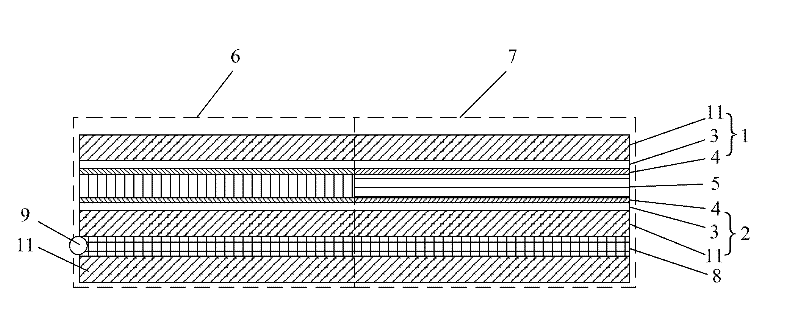
[0032] An embodiment of the present invention provides a transparent display device, such as figure 1 As shown, it includes: an upper substrate 1, which includes a glass substrate 11, a transparent electrode 3, and an alignment film 4 from top to bottom, and a lower substrate 2, which includes a glass substrate 11, a transparent electrode 3, and an alignment film from bottom to top. A film 4 and a color holographic polymer dispersed liquid crystal (Holographic Poly...


PUM


Abstract

The invention discloses a transparent display device, relating to the field of display, and capable of improving transmittance of the transparent display device. The transparent display device comprises an upper substrate, a lower substrate and a colour H-PDLC (holographic polymerdispersed liquid crystal) layer, wherein the upper substrate sequentially comprises a transparent electrode and an alignment film from top to bottom, the lower substrate sequentially comprises the transparent electrode and the alignment film from top to bottom, and the colour H-PDLC layer is arranged between the upper substrate and the lower substrate.

Description

technical field [0001] The invention relates to the display field, in particular to a transparent display device. Background technique [0002] With the development of display technology and the increasing demand for the use of portable information media, in recent years, so-called transparent display devices have been actively researched and developed. Objects behind the display can be seen through the display when no voltage is applied. [0003] In the process of realizing the present invention, the inventor finds that there are at least the following problems in the prior art: [0004] In the existing transparent display device structure, the liquid crystal molecules are located between two polarizers, and the electric field is used to control the rotation of the liquid crystal molecules to change the polarization direction of light, and cooperate with the polarizers to form different gray levels. However, the use of polarizers greatly reduces the transmittance of the t...

Claims


Application Information

Patent Timeline
Patent Type & Authority Applications(China)
IPC IPC(8): G02F1/1337G02F1/1343G02F1/133
CPCG02F1/13342G02F1/133723G02F1/13476
Inventor 鹿岛美纪
Owner BOE TECH GRP CO LTD
Why Eureka
Eureka Blog
Learn More