Cable wire barrow

A pay-off car and cable technology, which is applied to the installation of cables, the arrangement of cables between relative moving parts, and electrical components, etc. It can solve the problems of easy and labor-saving cables, labor-intensive, and difficult cable releases, and achieves a convenient axis. Orientation, simple and practical effect

Active Publication Date: 2012-09-05
HANGZHOU ELECTRIC EQUIP MFG +3
View PDF7 Cites 18 Cited by
  • Summary
  • Abstract
  • Description
  • Claims
  • Application Information

AI Technical Summary

Problems solved by technology

[0003] The purpose of the present invention is to overcome the problem that the current cable pay-off vehicle is difficult and laborious when the cable is thick and heavy and the path of the pay-off is rough and the tractor is difficult to walk, and to provide a thicker and heavier cable The cable pay-off vehicle is easy and labor-saving when the pay-off path is rough and uneven.

Method used


Image

  • Cable wire barrow
  • Cable wire barrow
  • Cable wire barrow

Examples


Embodiment Construction

[0025] The present invention will be further described below in conjunction with the accompanying drawings.

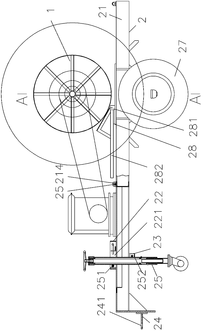
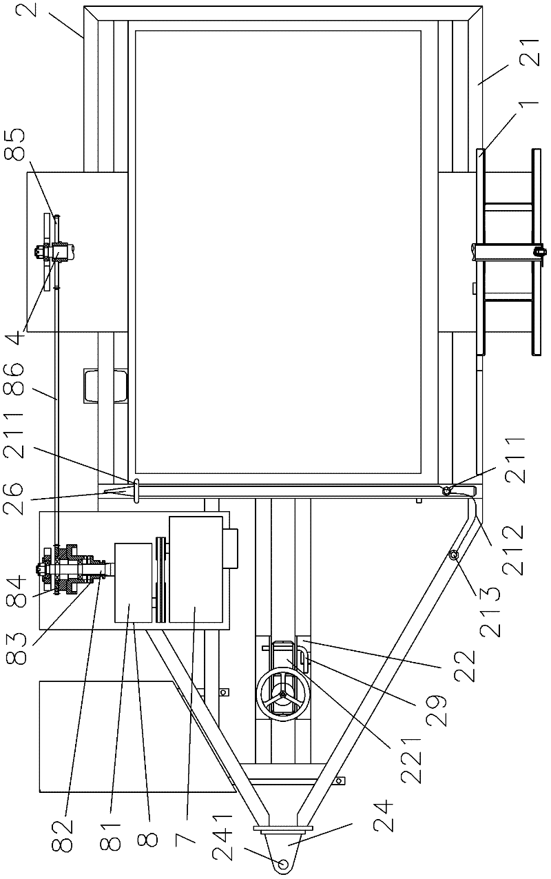
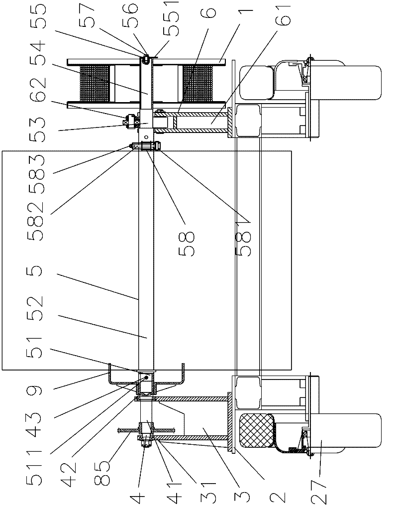
[0026] as attached figure 1 , attached figure 2 , attached image 3 Shown: a cable pay-off car, including a traction cable reel 1, a frame 2 with wheels 27, a support frame 3, a rotating shaft 4, a reel shaft 5, an opening and closing cage 6, and a driving device for driving the rotating shaft 4 7. Transmission device 8 and transmission fork 9.

[0027] The reel shaft 5 includes a connecting section 51 connected in sequence, a cable section 52 for installing a cable reel, a support section 53 and a traction section 54; the traction cable reel 1 is sleeved outside the traction section 54; the reel shaft 5 has A stopper 55, a washer 56, a set screw 57 and a locator 58 for axially fixing the cable reel with a diameter greater than the diameter of the traction section 54; the stopper 55 can be found in Figure 8 , has an open slot 551 with a width greater than the outer...


PUM


Abstract

The invention relates to the field of cable taking-up and paying-off equipment, and aims to provide a cable wire barrow of which a transmission mechanism between a power machine and a take-up drum has functions of overload protection and labor conservation by manually rotating the take-up drum. The cable wire barrow comprises a car frame with wheels, a bearing frame, a rotating shaft, a driving device which is used for driving the rotating shaft, a transmission device, a wire plate shaft, a traction rope plate, a transmission fork and an opening and closing retainer, wherein the wire plate shaft comprises a connecting section, a cable section, a bearing section and a traction section which are connected with one another in sequence; the rotating shaft comprises a transmission section and a supporting section; the transmission section of the rotating shaft is pivoted with the bearing frame, and the transmission fork is sleeved outside the supporting section and is fixedly connected with the supporting section; and the connecting section is detachably and fixedly connected with the supporting section, the opening and closing retainer bears the bearing section, and the traction rope plate is sleeved outside the traction section. The cable wire barrow ensures that the paying off of cables is easy and labor-saving when the cables are relatively thick and heavy and a paying-off path is bumpy.

Description

technical field [0001] The invention relates to the field of cable take-up and pay-off equipment, in particular to a cable pay-off vehicle with overload protection for the transmission mechanism between the power machine and the take-up reel and labor-saving manual rotation of the take-up reel. Background technique [0002] The cable is often wound on the cable reel, and when in use, the cable reel is installed on the rotating shaft of the support to pay off; because the location of the pay-off is often changed, it is very laborious to carry the support and the efficiency is low; Chinese patent announcement The utility model No. CN201319479 discloses a mobile cable pay-off vehicle; the mobile cable pay-off vehicle has a base, the front end of the base is provided with a tray connected to the tractor, the bottom of the base is provided with rollers and steering wheels, and the upper end of the base is There are a set of uprights and auxiliary brackets on both sides, a jack is...

Claims


Application Information

Patent Timeline
Patent Type & Authority Applications(China)
IPC IPC(8): H02G11/00H02G11/02
Inventor 陈敏李会荣蒋鲁军
Owner HANGZHOU ELECTRIC EQUIP MFG
Why Eureka
Try Eureka