Vehicle body floor structure

A vehicle body bottom plate and structure technology, applied in the direction of superstructure, substructure, vehicle parts, etc., can solve the problems of light weight of the body, narrowing of the interior space of the vehicle, and increase in the weight of the extension of the central frame, so as to expand the joint range, Effect of reducing air resistance and maintaining quiet performance

Active Publication Date: 2012-09-05
HONDA MOTOR CO LTD
View PDF8 Cites 17 Cited by
  • Summary
  • Abstract
  • Description
  • Claims
  • Application Information

AI Technical Summary

Problems solved by technology

However, if the strength of the center frame extension is increased, the weight of the center frame extension will increase, and there is a problem that it is contrary to the weight reduction of the vehicle body
Furthermore, since the cross-sectional area of ​​the central frame extension needs to be increased, there is a problem that the floor surface rises and the interior space of the vehicle becomes narrow.

Method used


Image

  • Vehicle body floor structure
  • Vehicle body floor structure
  • Vehicle body floor structure

Examples


Embodiment Construction

[0029] Next, embodiments of the present invention will be described with reference to the drawings.

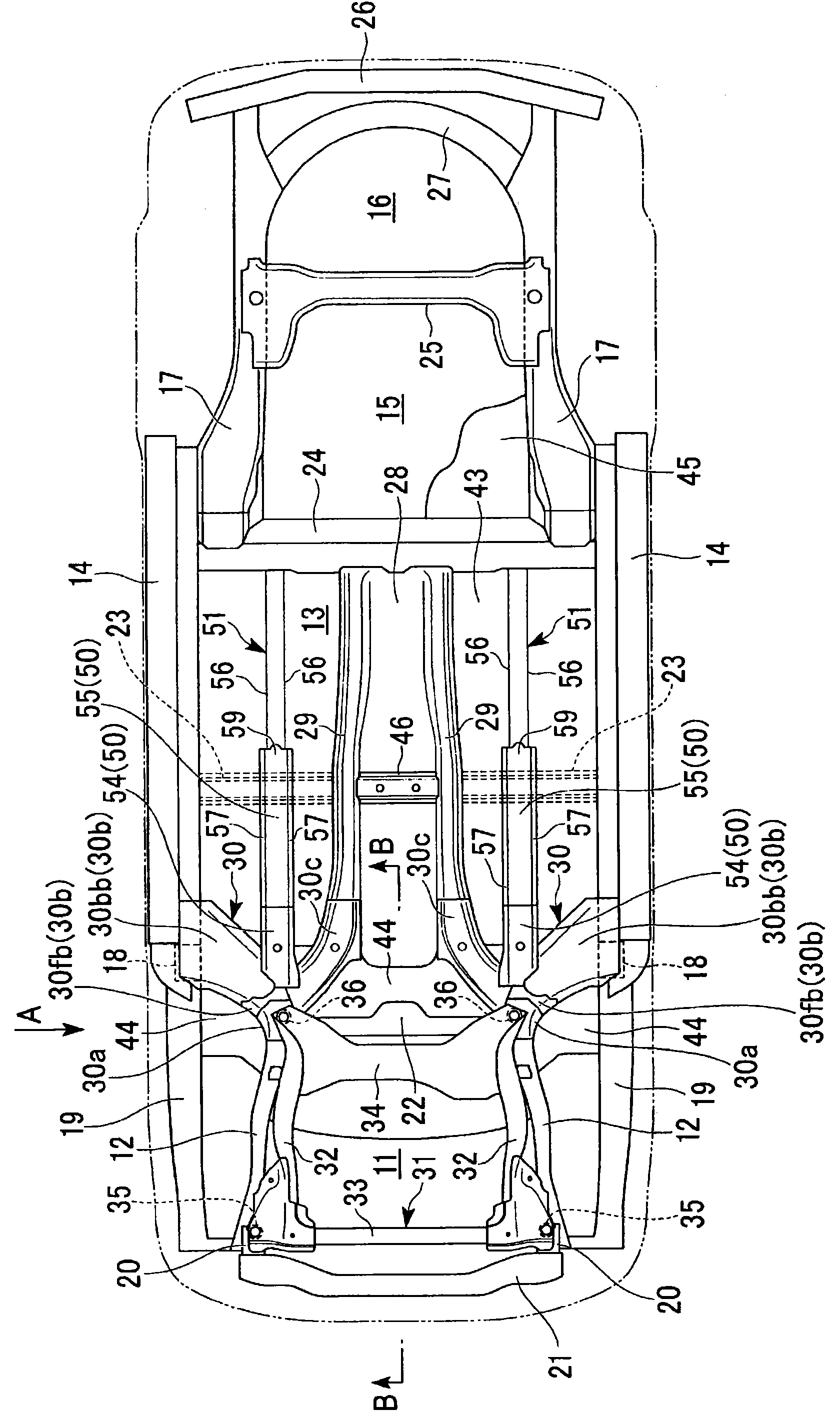
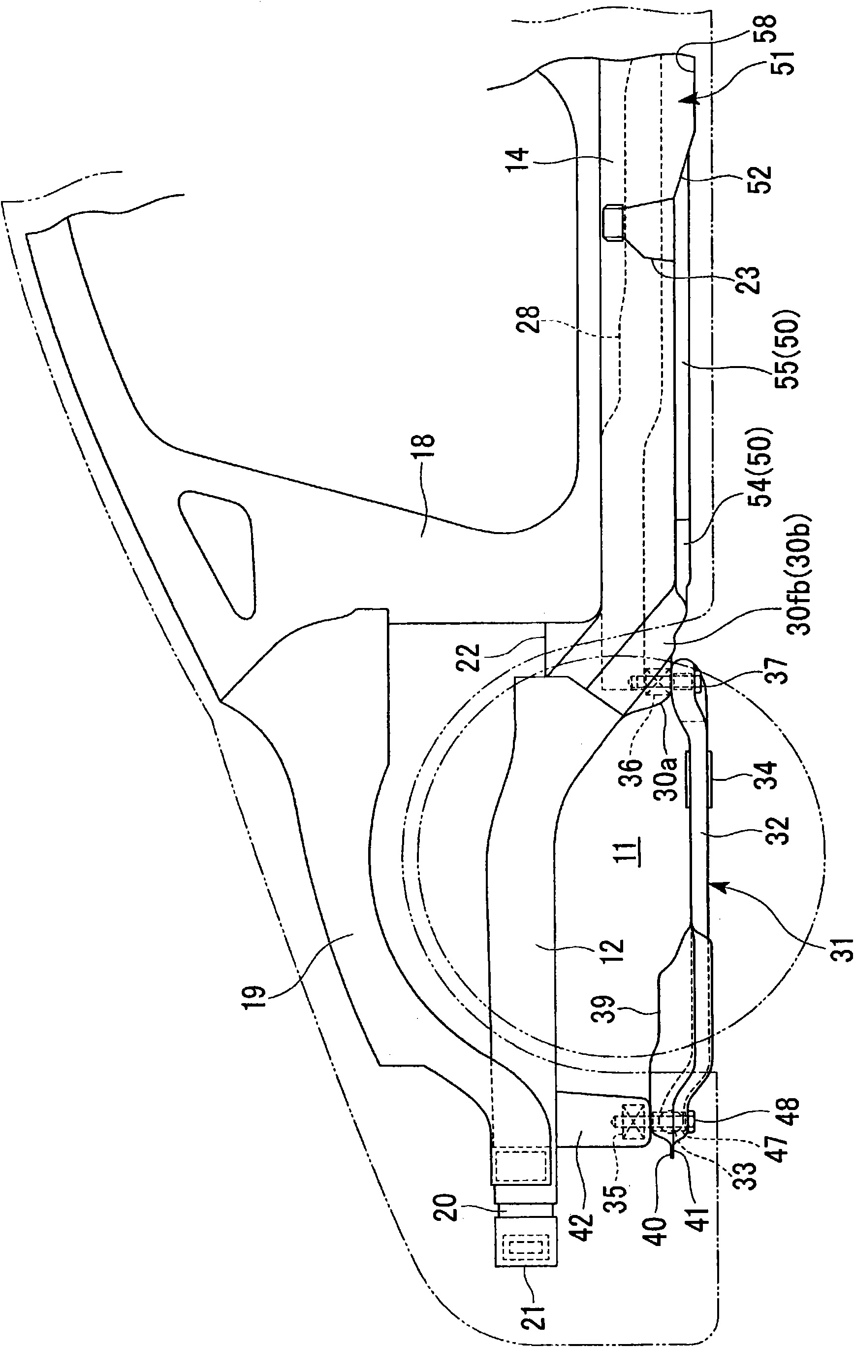
[0030] figure 1 is a diagram of a car body as viewed from below, figure 2 yes figure 1 A view from direction A. exist figure 1 , figure 2 The shape of the body is indicated by a dotted line. Such as figure 1 , figure 2 As shown, the body frame (underbody structure) of the automobile has: front side frames 12, 12; lower side members 14, 14; rear side frames 17, 17; front lower pillars 18, 18; .

[0031] The front side frames 12 , 12 extend in the front-rear direction of the vehicle body along the left and right sides of the engine room 11 , and have a pair of left and right closed cross-sectional structures. The side members 14 , 14 extend in the front-rear direction of the vehicle body along the left and right side portions of the cabin 13 , and have a pair of left and right closed cross-sectional structures. The rear side frames 17, 17 extend in the front-rear di...


PUM


Abstract

In this vehicle body floor structure, stiffeners that extend to a rear of a front cross member and that have a U-shaped concave portion that is open at to top thereof when viewed in a cross-section of a vehicle are joined to a bottom surface on both side portions of floor panel. Beads that have a U-shaped concave portion when viewed in a cross-section of the vehicle are provided at a rear portion of the floor panel, and the beads are aligned with the concave portion of the stiffeners and are provided continuously with the stiffeners.

Description

technical field [0001] The invention relates to an underbody structure. [0002] This application claims priority based on Japanese Patent Application No. 2009-285134 for which it applied in Japan on December 16, 2009, and uses the content here. Background technique [0003] There is known a vehicle body structure comprising: front frames arranged along the front-rear direction of the vehicle body on both sides of an engine compartment; side sills arranged along the front-rear direction of the vehicle body on both sides of the compartment ; and a center frame arranged along the front-rear direction of the vehicle body on the central part of the vehicle body in the width direction of the vehicle body. In this vehicle body structure, there is provided a connecting member that connects the rear end portion of the front side frame, the front end portion of the side sill, and the front end portion of the center frame. [0004] The connecting member has: an outrigger extending o...

Claims


Application Information

Patent Timeline
Patent Type & Authority Applications(China)
IPC IPC(8): B62D25/20
CPCB62D21/11B62D25/20B62D21/152B62D25/2018
Inventor 安原重人安藤公贵松浦裕志菅原克也
Owner HONDA MOTOR CO LTD
Why Eureka
Try Eureka