Base component of bladeless fan

A bladeless fan and component technology, applied in the direction of machines/engines, non-displacement pumps, mechanical equipment, etc., can solve the problems of complex structure of the fan base, and achieve the effect of simple structure, stable and reliable performance

Inactive Publication Date: 2014-12-31
NINGBO X K L ELECTRIC APPLIANCE CO LTD
View PDF9 Cites 9 Cited by
  • Summary
  • Abstract
  • Description
  • Claims
  • Application Information

AI Technical Summary

Problems solved by technology

The basic structure of the bladeless fan includes a barrel, a turbocharger motor and an annular nozzle. The turbocharger motor is set in the barrel, and the airflow from the turbocharger motor is sprayed outward through the annular nozzle. The airflow emitted from the top is sucked through the opening, and finally the air blown out from the fan flows in the horizontal direction. In order to realize the adjustment of the air outlet direction, a rotating mechanism and a swinging mechanism are set on the base of the bladeless fan. The rotating mechanism is used to adjust the level of the fan. direction, the swing mechanism is used to adjust the pitch angle of the fan, and the base of the bladeless fan is equipped with a rotation mechanism and a swing mechanism at the same time, which makes the structure of the fan base more complicated

Method used


Image

  • Base component of bladeless fan
  • Base component of bladeless fan
  • Base component of bladeless fan

Examples


Embodiment Construction

[0023] The present invention will be further described in detail below in conjunction with the accompanying drawings and embodiments.

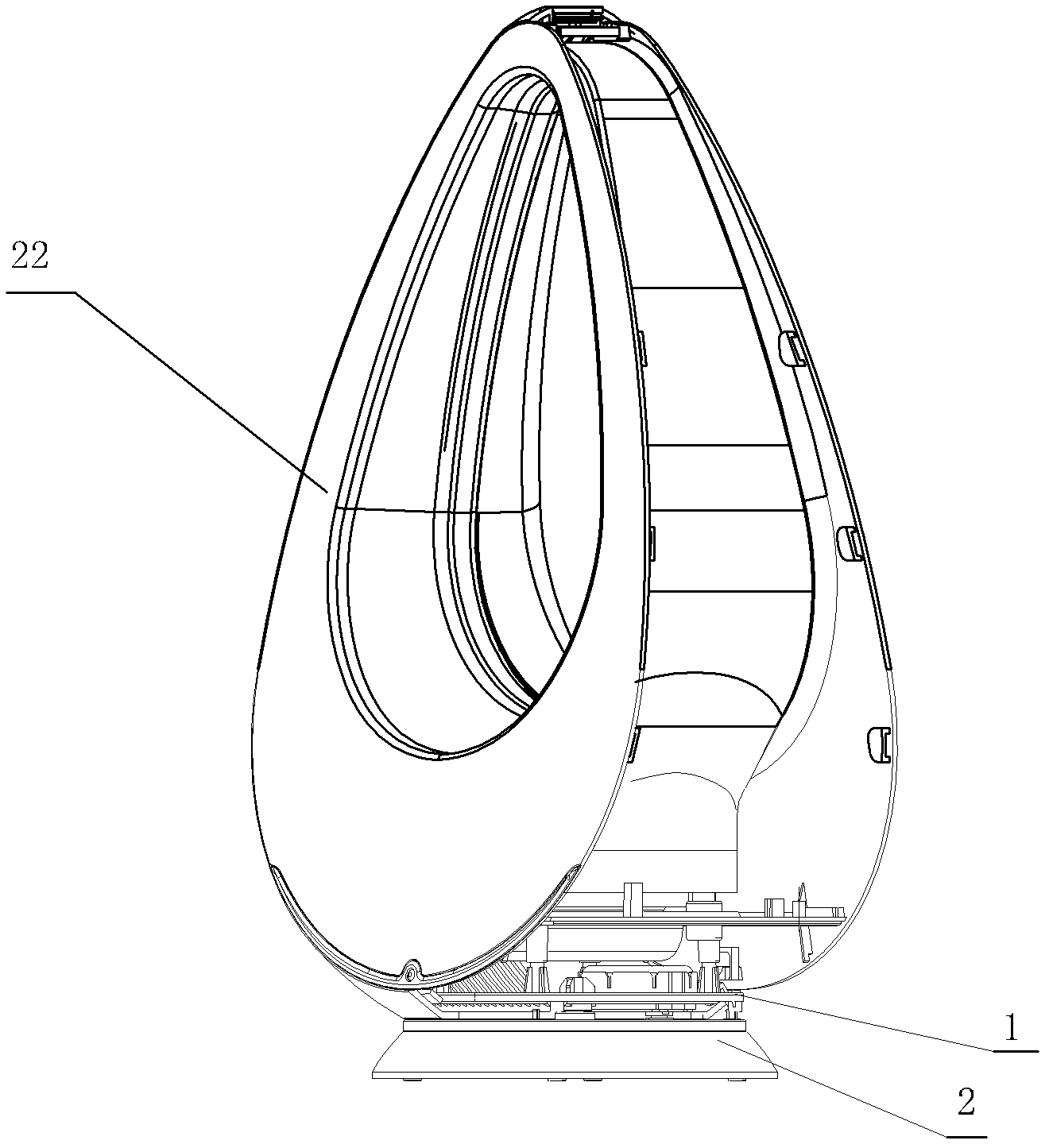
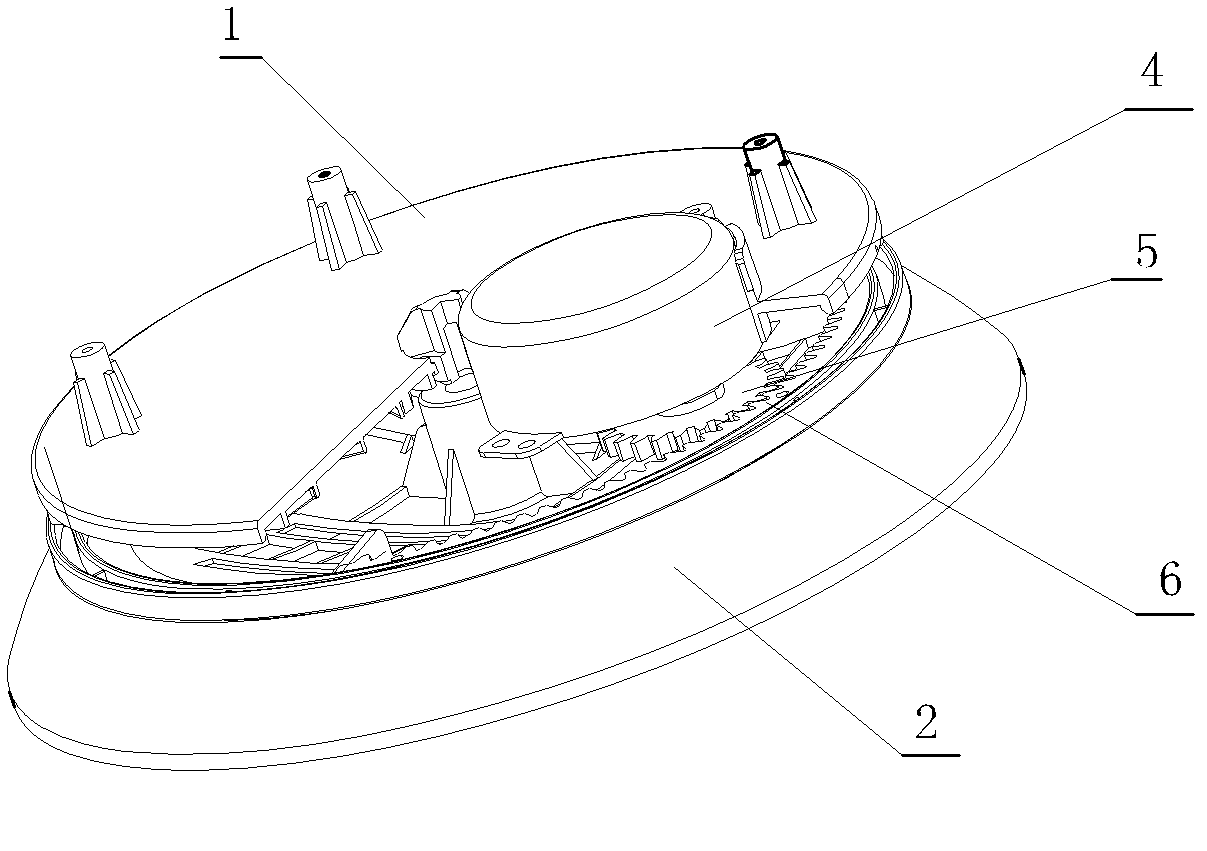
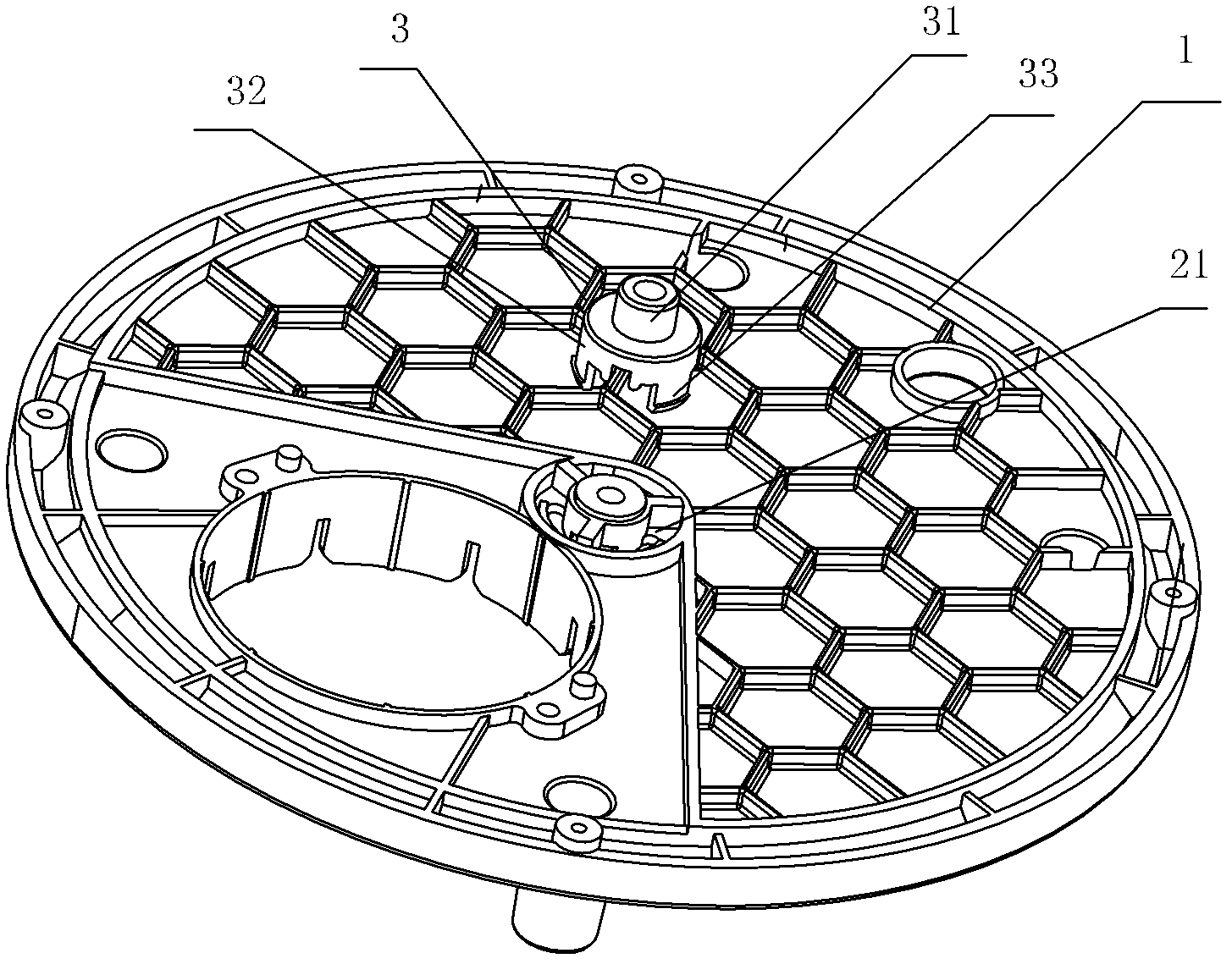
[0024] A base assembly for a bladeless fan, including a rotating disk 1 and a chassis assembly 2 for supporting a fan assembly 22, the center of the rotating disk 1 is pivotally connected to the center of the chassis assembly 2 through a rotating shaft assembly 3, and the rotating disk 1 is located at the bottom of the chassis assembly 2 Above, the rotating disk 1 is provided with a motor 4, and a rotating mechanism is arranged between the rotating disk 1 and the chassis assembly 2. The motor 4 drives the rotating mechanism to rotate the rotating disk 1. The chassis assembly includes a fixed base 7 and a movable disk 8, and the fixed base 7 The upper surface of the upper surface is a concave spherical surface, the lower surface of the movable disk 8 is a convex spherical surface, the upper surface of the fixed base 7 cooperates with the lower s...


PUM


Abstract

The invention discloses a base component of a bladeless fan. The base component comprises a rotating plate and a base plate component, the rotating plate is used for supporting a fan component, the center of the rotating plate is axially connected to the center of the base plate component by a rotating shaft component, the rotating plate is positioned above the base plate component, a motor is disposed on the rotating plate, a rotating mechanism is arranged between the rotating plate and the base plate component, a motor drives the rotating mechanism to enable the rotating plate to rotate, the base plate component consists of a fixed base and a movable plate, the upper surface of the fixed base is an inwards concave spherical surface, the lower surface of the movable plate is an outwards convex spherical surface, the upper surface of the fixed base and the lower surface of the movable plate match with each other, and a sliding mechanism is arranged between the fixed base and the movable plate. The base component of the bladeless fan has the advantages that the motor drives the rotating mechanism to enable the rotating plate to rotate, accordingly, the fan component rotates, an annular nozzle in the fan component rotates, and the horizontal air outlet direction of the fan is adjusted; and the movable plate can move on the fixed base owing to the sliding mechanism, so that the fan component can be inclined forwards or backwards, and the air outlet pitching angle of the fan can be adjusted.

Description

technical field [0001] The invention relates to a bladeless fan, in particular to a base assembly of the bladeless fan. Background technique [0002] Compared with traditional electric fans, bladeless fans have the characteristics of low noise and good safety. The basic structure of the bladeless fan includes a barrel, a turbocharger motor and an annular nozzle. The turbocharger motor is set in the barrel, and the airflow from the turbocharger motor is sprayed outward through the annular nozzle. The airflow emitted from the top is sucked through the opening, and finally the air blown out from the fan flows in the horizontal direction. In order to realize the adjustment of the air outlet direction, a rotating mechanism and a swinging mechanism are set on the base of the bladeless fan. The rotating mechanism is used to adjust the level of the fan. direction, the swing mechanism is used to adjust the pitch angle of the fan, and the base of the bladeless fan is equipped with a ...

Claims


Application Information

Patent Timeline
Patent Type & Authority Patents(China)
IPC IPC(8): F04F5/44
Inventor 魏建峰
Owner NINGBO X K L ELECTRIC APPLIANCE CO LTD
Why Eureka
Try Eureka