Zero-crossing detection method and circuit

A zero-crossing detection circuit and zero-crossing detection technology are applied in the direction of measuring electrical variables, measuring current/voltage, measuring devices, etc., which can solve the problems of long conduction time and high power consumption of optocoupler U1, and achieve low power consumption, The effect of short on-time

Inactive Publication Date: 2012-09-12
HUAWEI TECH CO LTD
View PDF8 Cites 21 Cited by
  • Summary
  • Abstract
  • Description
  • Claims
  • Application Information

AI Technical Summary

Problems solved by technology

[0005] However, in the process of realizing the above-mentioned zero-crossing detection, the inventor found that there are at least the following problems in the prior art: because the time for the mains voltage to be higher than the conduction voltage of the optocoupler U1 is relatively long, that is figure 1 The photocoupler U1 in the zero-crossing detection circuit shown has a long conduction time, so the power consumption is very high

Method used


Image

  • Zero-crossing detection method and circuit
  • Zero-crossing detection method and circuit
  • Zero-crossing detection method and circuit

Examples


Embodiment 1

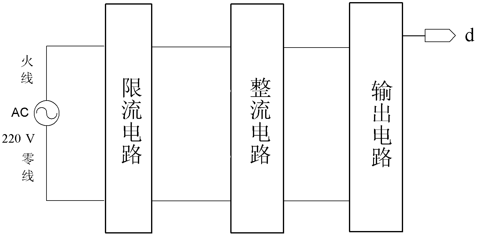
[0032] Embodiment 1 of the present invention provides a schematic diagram of the principle of a zero-crossing detection circuit for implementing the above-mentioned zero-crossing detection method, as shown in image 3 As shown, the entire zero-crossing detection circuit includes the live wire and neutral wire of the commercial power, the live wire and neutral wire of the commercial power are connected to a rectifier circuit, and the rectifier circuit is connected to an output circuit, and between the live wire and neutral wire of the commercial power and the rectifier circuit Connect a current limiting circuit.

[0033] The zero-crossing detection circuit provided by Embodiment 1 of the present invention greatly reduces the current of the entire zero-crossing detection circuit through the strong current-limiting effect of the current-limiting circuit, so that the zero-crossing detection circuit is turned on when the mains voltage is close to the peak value. Therefore, the cond...

Embodiment 2

[0040]Embodiment 2 of the present invention provides another schematic diagram of a zero-crossing detection circuit implementing the above-mentioned zero-crossing detection method, as shown in Figure 5 As shown, different from Embodiment 1, the zero-crossing detection circuit of this embodiment also includes a low-pass filter circuit and a voltage stabilization protection circuit, the low-pass filter circuit is connected between the current limiting circuit and the rectification circuit, and the voltage stabilization protection circuit Connected between the low-pass filter circuit and the rectifier circuit.

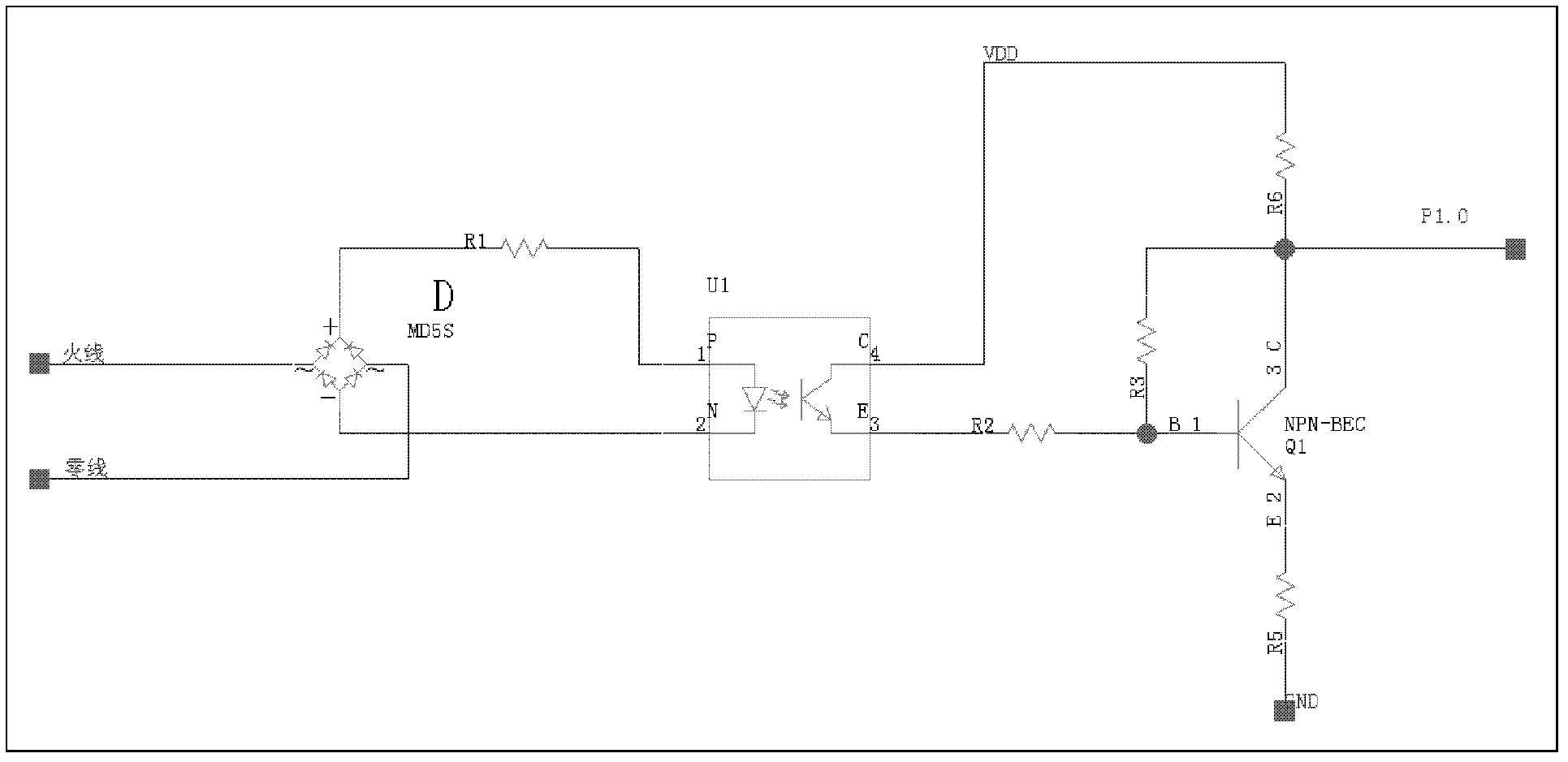
[0041] The specific implementation circuit schematic diagram of the zero-crossing detection circuit provided by Embodiment 2 of the present invention is as follows Figure 6 As shown, the difference from the specific realization circuit of embodiment 1 is that Figure 6 The circuit shown specifically also includes an RC low-pass filter circuit composed of a resistor R3 ...

Embodiment 1 and Embodiment 2

[0043] Below in conjunction with embodiment 1 and embodiment 2, the method for detecting zero-crossing point is explained in detail:

[0044] Such as Figure 7 Shown is the timing diagram of the zero-crossing detection circuit of Embodiment 2. combine Figure 6 It can be seen that when the mains power supply is powered on, the signal measured at point a is a 220V sine wave, and the point b after the half-bridge rectification has only a positive signal. After the optocoupler U1 is turned on, the voltage at point c is pulled down, and at c The optocoupler U1 at the point will output a negative pulse signal, and finally output a positive pulse signal after the inversion of Q1.

[0045] Since the frequency of the commercial power is 50Hz, according to the above peak detection principle, the period of the generated pulse signal is 20ms, that is Figure 6 Middle t2-t0=20ms; According to Figure 6 The circuit shown finally obtains t1-t0=Δt of the pulse signal; calculates the volt...


PUM


Abstract

The embodiment of the invention discloses a zero-crossing detection method and a circuit, relates to the field of power line communication and control, and aims to solve the problem of high power consumption of a zero-crossing detection circuit in the prior art. The zero-crossing detection method comprises the steps of detecting the time point t0 at which the mains voltage jumps from a low level to a high level at the port of a detection end and the adjacent time point t1 at which the mains voltage jumps from the high level to the low level, and determining the time point t at which the mains voltage passes the zero point. The zero-crossing detection circuit comprises a live wire and a null wire of a commercial power, wherein the live wire and the null wire of the commercial power are connected with a rectification circuit, the rectification circuit is connected with an output circuit, and a current limit circuit is connected between the live line and the null line of the commercial power and the rectification circuit. The zero-crossing detection method and the circuit are used for zero-crossing detection of a mains network.

Description

technical field [0001] The invention relates to the field of power line communication and control, in particular to a zero-crossing detection method and circuit. Background technique [0002] In power line communication, it is necessary to control the communication synchronously through a unified time point. A unified time reference can be determined by detecting the time point when the mains passes through the zero point, so that the communication can be synchronously controlled. Therefore, the zero-crossing detection of the mains power becomes An integral part of power line communications. [0003] At present, there are many schemes for zero-crossing detection circuit. Such as figure 1 Shown is a zero-crossing detection circuit in the prior art. exist figure 1 Among them, the live wire of the mains network is connected to the first pin of the bridge rectifier circuit D, and the neutral line of the mains network is connected to the third pin of the bridge rectifier circ...

Claims


Application Information

Patent Timeline
Patent Type & Authority Applications(China)
IPC IPC(8): G01R19/175
CPCG01R19/175H03K5/1536
Inventor 姚国良马震宇
Owner HUAWEI TECH CO LTD
Why Eureka
Try Eureka