Multiphase resonant converter for dc-dc applications

a multi-phase resonant converter and converter technology, applied in the field of converters, can solve the problems of reducing the efficiency of the converter and limiting the application of the converter, and achieve the effects of reducing conduction losses, increasing the efficiency of the multi-phase resonant converter, and small curren

Active Publication Date: 2008-12-04
RGT UNIV OF CALIFORNIA
View PDF11 Cites 93 Cited by
  • Summary
  • Abstract
  • Description
  • Claims
  • Application Information

AI Technical Summary

Benefits of technology

[0009]During operation, the current of the multiphase converter is shared among the unit converters, resulting in a smaller current in each unit converter. The smaller current in each unit converter reduces conduction losses, thereby increasing the efficiency of the multiphase resonant converter. In addition, the smaller current in each unit converter reduces the amount of stress placed on semiconductor switches and other individual components of the converter allowing for the use of lower tolerance components. Further, the multiphase converter has automatic current sharing ability without the need for additional current sensor and control circuitry.
[0010]The multiphase resonant converter provides the above advantages over conventional LLC series resonant converters while preserving desirable features of conventional LLC series resonant converters including zero voltage switching at both inverter and rectifier sides, wide load range, and fast transient response.

Problems solved by technology

However, the large circulation currents in LLC series resonant converters limit their application.
Further, the large circulation currents increase conduction losses, reducing the efficiency of the converters.

Method used


Image

  • Multiphase resonant converter for dc-dc applications
  • Multiphase resonant converter for dc-dc applications
  • Multiphase resonant converter for dc-dc applications

Examples


Embodiment Construction

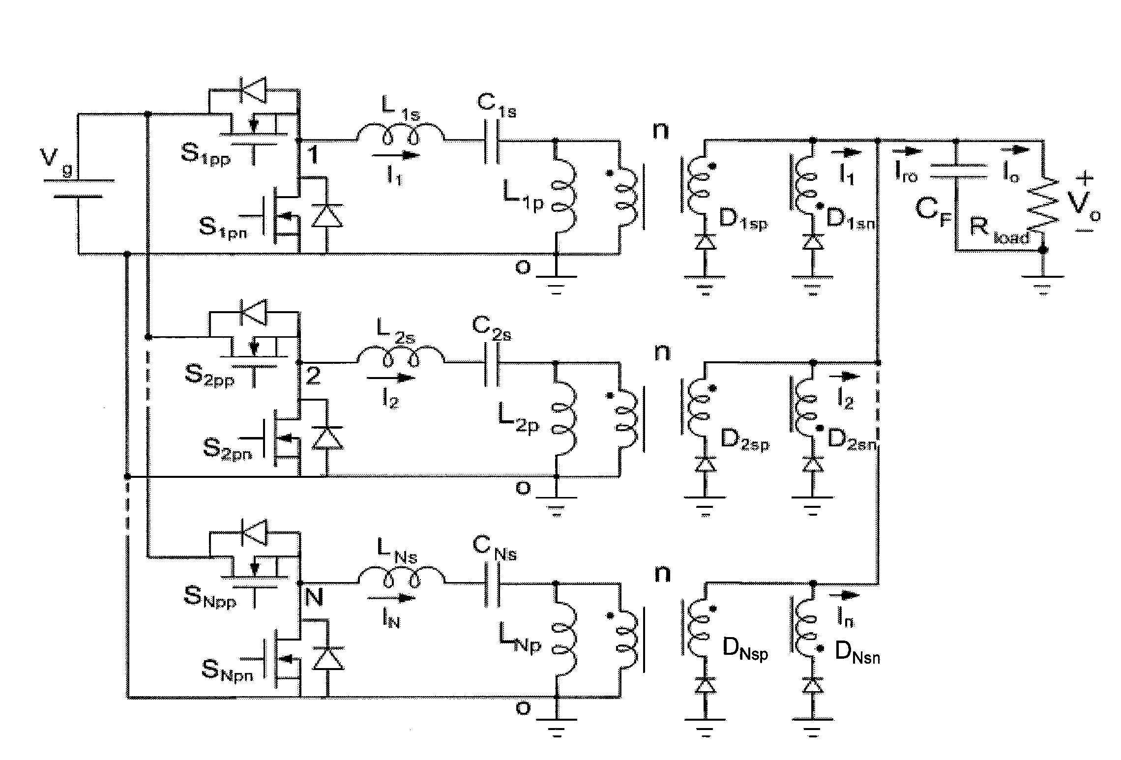
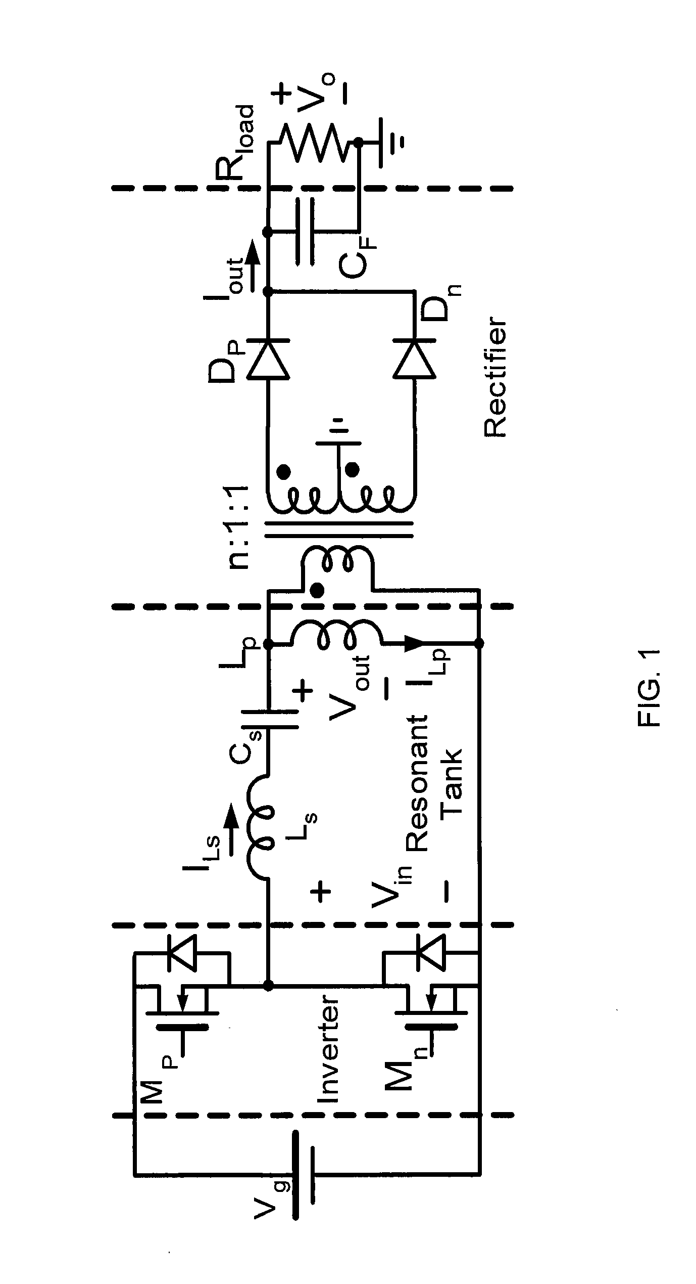
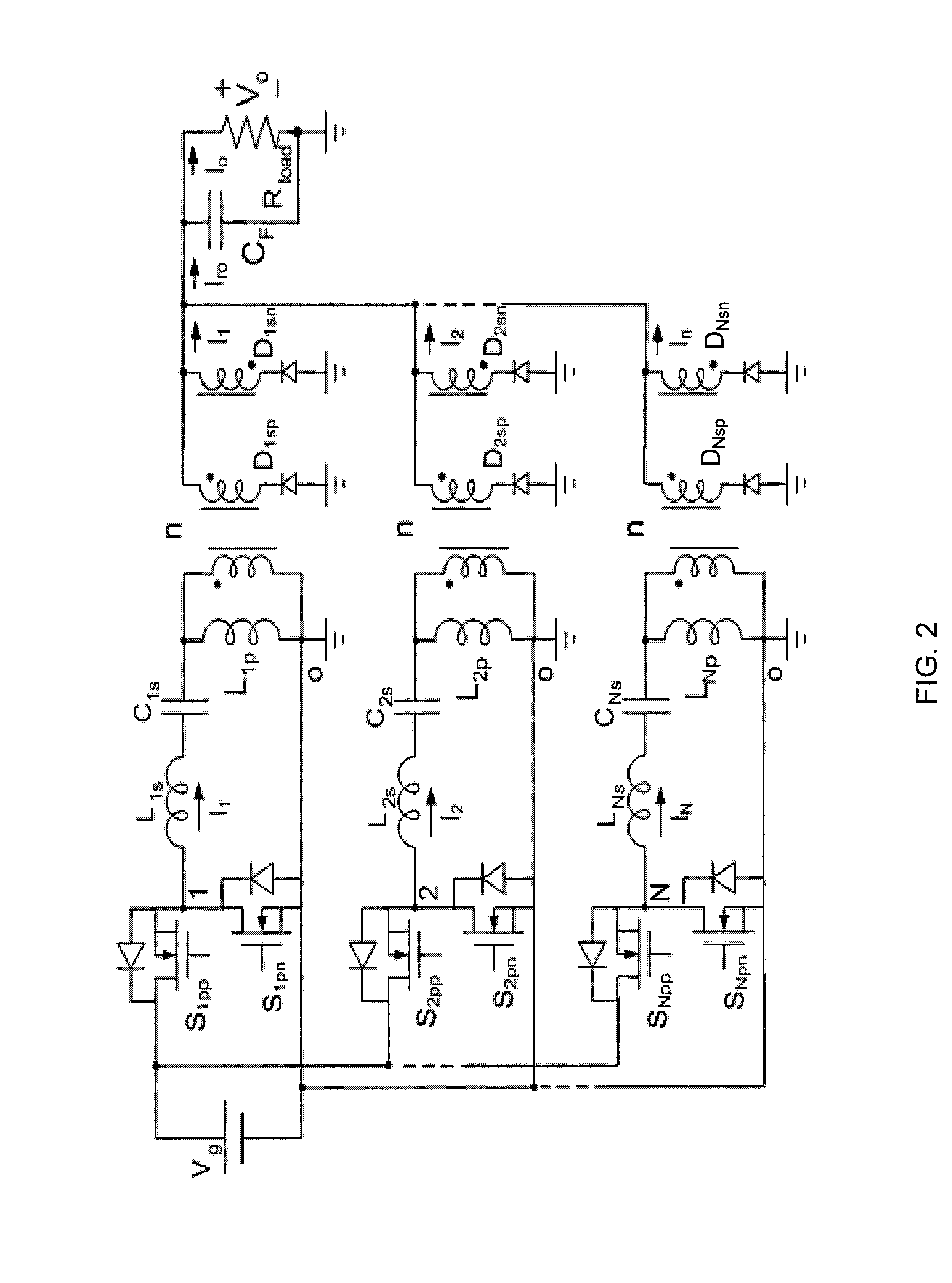
[0028]To satisfy high current, high efficiency, fast transient, and low profile requirement for dc-dc conversion, new converters are provided targeting the following features: 1) Voltage fed inverter stage for fast transient response and lower voltage stress; 2) ZVS switching resonant power stage for high frequency (˜2 MHz) high efficiency operation; 3) Bipolar, naturally balanced transformer operation, with lowest possible turns ratio and minimal number of windings; 4) Narrow switching frequency range (if resonant topologies are used); 5) Synchronous rectifier (SR) for high efficiency; and 6) Multi phases with automatic current sharing and low output current ripple.

[0029]The various embodiments and example provided herein are generally directed to novel multiphase resonant converters that overcome limitations of conventional LLC series resonant converters while preserving desirable features of conventional LLC series resonant converters including zero voltage switching at both inve...


PUM


Abstract

The various embodiments and example provided herein are generally directed to novel multiphase resonant converters. In an embodiment, a multiphase resonant converter comprises N unit resonant converters having inputs and outputs connected in parallel, respectively. Each unit converter comprises an inverter, a LLC series resonant tank, and a rectifier. In a preferred embodiment, the inverters of the N unit converters are driven by N drive signals phase-shifted 2π / N degrees apart. During operation, the current of the multiphase converter is shared among the unit converters, resulting in a smaller current in each unit converter. The smaller current in each unit converter reduces conduction losses, thereby increasing the efficiency of the multiphase converter. In addition, the smaller current in each unit converter reduces the amount of stress placed on individual components of the converter allowing for the use of lower tolerance components. Further, the multiphase converter has automatic current sharing ability.

Description

RELATED APPLICATION[0001]This application claims the benefit of provisional application 60 / 940,926 filed on May 30, 2007, the specification of which is incorporated in its entirety herein by reference.FIELD OF THE INVENTION[0002]The present invention related to converters and, more particularly, to multiphase resonant converters for dc-dc applications.BACKGROUND INFORMATION[0003]Dc-dc converters are used to convert one voltage to another voltage level. Applications for dc-dc converters include converting dc power from a battery to a lower voltage to power circuits in a portable electronic device, e.g., cell phone.[0004]FIG. 1 shows the basic topology of a conventional LLC series resonant converter for converting a voltage at its input Vg to another voltage Vo at its output. The LLC series resonant converter comprises an inverter, an LLC series resonant tank, and a rectifier. The inverter is realized by a half-bridge inverter with switches Mp and Mn that are driven complementary to g...

Claims


Application Information

Patent Timeline
Patent Type & Authority Applications(United States)
IPC IPC(8): H02M7/06H02M3/335
CPCH02M3/285H02M2001/0058Y02B70/1491H02M1/0058Y02B70/10
Inventor JIN, TAOTAOSMEDLEY, KEYUE
Owner RGT UNIV OF CALIFORNIA
Why Eureka
Try Eureka