Electromechanical generator for converting mechanical vibrational energy into electrical energy

a technology of electrical energy and mechanical vibration, which is applied in the direction of machines/engines, mechanical equipment, mechanical circuit shapes/forms/construction, etc., can solve the problem that the device is not designed for use as an electromechanical generator, and achieve the effect of low eddy current and high moving mass

Active Publication Date: 2009-09-08
HITACHI RAIL LTD +1
View PDF17 Cites 96 Cited by
  • Summary
  • Abstract
  • Description
  • Claims
  • Application Information

AI Technical Summary

Benefits of technology

[0016]Preferably, the circuitry is encapsulated within the annular recess by a sealing material, which seals and protects the circuitry against undesired environmental influences.
[0032]In the electromechanical generator of the preferred embodiment of the present invention a high moving mass can be achieved by filling almost all of the internal space with a metallic magnetic core assembly. This can be achieved at least partly because flat springs at opposed ends of the magnetic core assembly are volume efficient. In addition, a high Q comes from the fact that the “enclosed” structure of the magnetic core assembly leaks very little flux, and so there is very little eddy current in the surrounding material of the stationary housing. Accordingly, little clearance needs to be kept between the moving magnetic core assembly and the housing, allowing more moving mass. A high magnetic coupling comes also from the enclosed nature of the magnetic core assembly where very little flux leaks out—almost all the magnetic flux gets channeled though the coil.

Problems solved by technology

Such a device is not designed for use as an electromechanical generator for efficiently harvesting a high amount of electrical power from ambient vibrations, e.g. for powering wireless sensors.

Method used


Image

  • Electromechanical generator for converting mechanical vibrational energy into electrical energy
  • Electromechanical generator for converting mechanical vibrational energy into electrical energy
  • Electromechanical generator for converting mechanical vibrational energy into electrical energy

Examples


Embodiment Construction

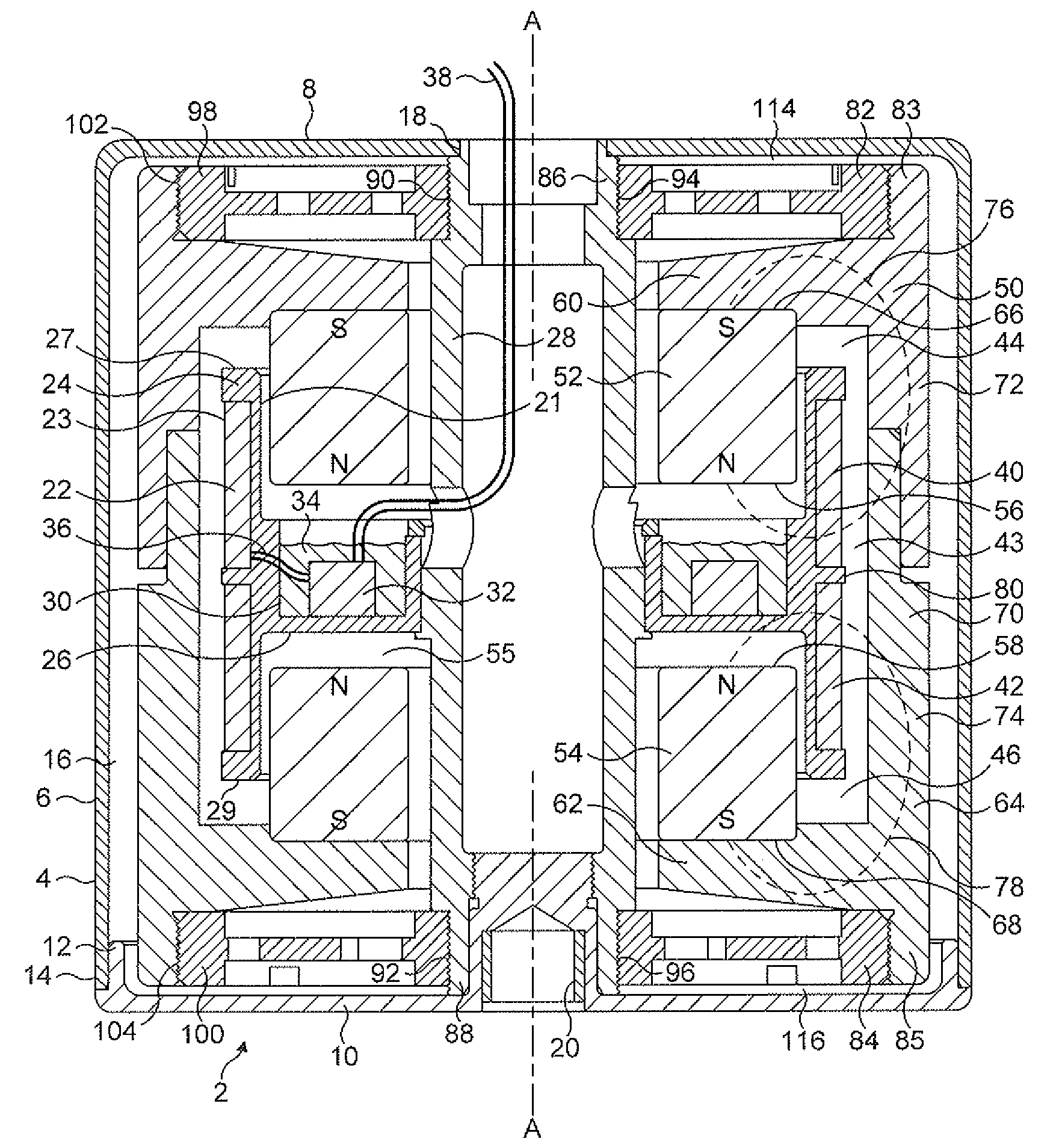
[0039]The electromechanical generator of the present invention is a resonant generator known in the art as “velocity-damped” where all of the work done by the movement of the inertial mass relative to the housing is proportional to the instantaneous velocity of that movement. Inevitably, a portion of that work is absorbed overcoming unwanted mechanical or electrical losses, but the remainder of the work may be used to generate an electrical current via a suitable transduction mechanism, such as the electrical coil / magnetic assembly described below.

[0040]FIGS. 1 to 3 show an electromechanical generator 2 for converting mechanical vibrational energy into electrical energy in accordance with a first embodiment of the present invention. 1. The electromechanical generator 2 comprises a housing 4. The housing 4 comprises an annular outer peripheral wall 6, an integral circular lid 8 and a circular base 10. The base 10 is securely fitted at its circular edge 12 to a lower edge 14 of the ou...


PUM


Abstract

An electromechanical generator for converting mechanical vibrational energy into electrical energy, the electromechanical generator comprising a housing, an electrically conductive coil assembly fixedly mounted in the housing, the coil assembly having radially inner and outer sides, and upper and lower edges, thereof, a mount for the coil assembly extending inwardly of the radially inner side for fixing the coil assembly in a fixed position in the housing, a magnetic core assembly movably mounted in the housing for linear vibrational motion along an axis, and a biasing device mounted between the housing and the magnetic core assembly to bias the magnetic core assembly in opposed directions along the axis towards a central position, wherein the magnetic core assembly encloses the electrically conductive coil assembly on the radially outer side and on the upper and lower edges, and on a part of the radially inner side, the magnetic core assembly having a gap on a radially inner portion thereof through which the mount extends, and the radially inner portion including two opposed magnets spaced along the axis.

Description

BACKGROUND TO THE INVENTION[0001]The present invention relates to an electromechanical generator for converting mechanical vibrational energy into electrical energy. In particular, the present invention relates to such a device which is a miniature generator capable of converting ambient vibration energy into electrical energy for use, for example, in powering intelligent sensor systems. Such a system can be used in many areas where there is an economical or operational advantage in the elimination of power cables or batteries.DESCRIPTION OF THE PRIOR ART[0002]It is known to use an electromechanical generator for harvesting useful electrical power from ambient vibrations, e.g. for powering wireless sensors. A typical magnet-coil generator consists of a spring-mass combination attached to a magnet or coil in such a manner that when the system vibrates, a coil cuts through the flux formed by a magnetic core.[0003]It is generally known in the art that as a rule the greater the mass of ...

Claims


Application Information

Patent Timeline
Patent Type & Authority Patents(United States)
IPC IPC(8): H02K35/02
CPCH02K35/02H02K1/34H02K5/12
Inventor ROBERTS, STEPHEN
Owner HITACHI RAIL LTD
Why Eureka
Try Eureka