Method for calibrating and optimizing camera parameters of vision measuring system

A technology of camera parameters and optimization methods, applied in the field of visual measurement, can solve the problem of non-convergence calculation amount, achieve high measurement accuracy, accelerate convergence speed, and improve program running efficiency.

Inactive Publication Date: 2012-09-12
BEIJING INFORMATION SCI & TECH UNIV
View PDF3 Cites 37 Cited by
  • Summary
  • Abstract
  • Description
  • Claims
  • Application Information

AI Technical Summary

Problems solved by technology

[0004] The direct linear transformation method (DLT method) requires a high-precision three-dimensional target, which has high requirements for the machining accuracy of the calibration target; two-step method (such as the radial alignment constraint (RAC) method), Zhang Zhengyou's two-dimensional plane All ca

Method used


Image

  • Method for calibrating and optimizing camera parameters of vision measuring system
  • Method for calibrating and optimizing camera parameters of vision measuring system
  • Method for calibrating and optimizing camera parameters of vision measuring system

Examples


Embodiment Construction

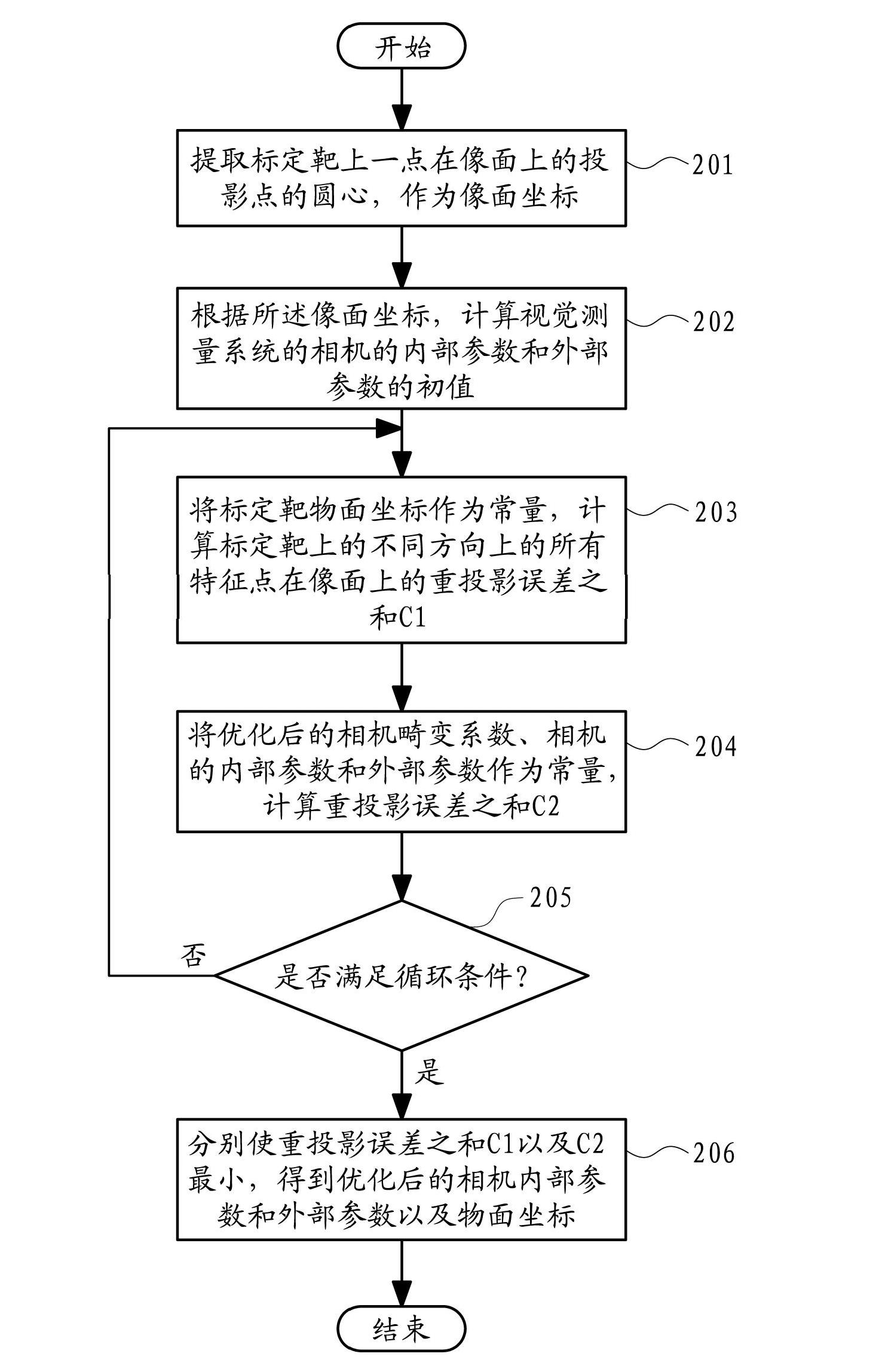
[0020] Hereinafter, embodiments of the present invention will be described in detail with reference to the drawings.

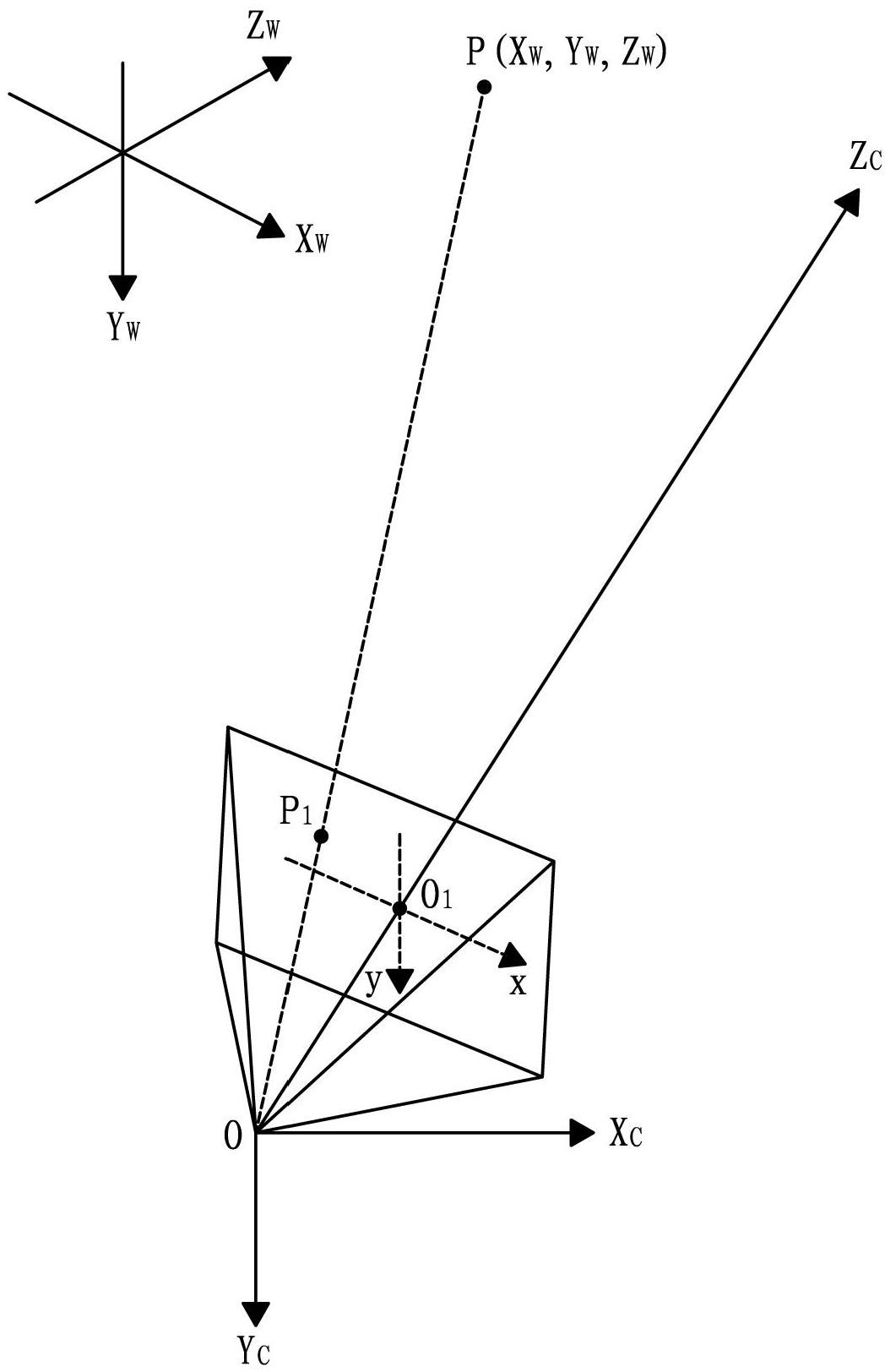
[0021] First, define the concept of three coordinate systems of the visual measurement system. The three coordinate systems are world coordinate system, camera coordinate system and image coordinate system. figure 1 A schematic diagram showing the relationship (geometric imaging relationship) between the three coordinate systems of the vision measurement system.

[0022] The world coordinate system is the reference coordinate system describing the position of the camera of the visual measurement system, such as figure 1 X in w , Y w ,Z w axis coordinate system. The camera coordinate system refers to the coordinate system with the camera optical center O as the origin; figure 1 , by point O and X c , Y c ,Z c The Cartesian coordinate system composed of axes forms the camera coordinate system. The image coordinate system refers to the coordinate system...


PUM


Abstract

The invention provides a method for calibrating and optimizing camera parameters of a vision measuring system. The method comprises the following steps of: (1) extracting a circle center of a projection point of one point on a calibration target on an image surface as an image surface coordinate; calculating initial values of internal parameters and external parameters of a camera of the vision measuring system according to the image surface coordinate; (3) optimizing camera distortion coefficients and the internal parameters and the external parameters of the camera by taking an object surface coordinate of the calibration target as constants, and calculating the sum C1 of reprojection errors of all feature points in the different directions on the calibration target on the image surface; (4) optimizing the object surface coordinate of the calibration target by taking the optimized camera distortion coefficients and the internal parameters and the external parameters of the camera as constants and taking the object surface coordinate of the calibration target as variables, and calculating the sum C2 of reprojection errors; (5) selecting cycle conditions, and returning to the step (3) if the cycle conditions are untenable; and (6) making the sum C1 and the sum C2 of the reprojection errors minimum respectively, and thus acquiring the optimized internal parameters and external parameters of the camera and the object surface coordinate.

Description

technical field [0001] The invention belongs to the field of visual measurement, and relates to a camera calibration method of a visual measurement system, and is especially suitable for a camera calibration system with low manufacturing precision of a calibration target. Background technique [0002] Visual measurement has the advantages of non-contact, fast measurement speed, convenience and flexibility, etc. It has important significance and broad application prospects in the fields of virtual reality and industrial inspection. In the visual measurement system, the process of the camera collecting images and calculating the three-dimensional information of the measured object is its most important measurement purpose, and the internal parameters such as the focal length and optical center of the camera, as well as the external parameters such as the rotation matrix and translation matrix are very important for the three-dimensional information of the object. The calculati...

Claims


Application Information

Patent Timeline
IPC IPC(8): G06T7/00
Inventor 娄小平吕乃光赵烨昕孙鹏
Owner BEIJING INFORMATION SCI & TECH UNIV
Why Eureka
Try Eureka