Hand-held power tool

A hand-held machine tool and tool technology, applied in the direction of motor tools, manufacturing tools, wrenches, etc., can solve the problems of high measurement technology costs and adjustment technology costs, and achieve the effects of low price, reduced manufacturing time, and simple mechanism

Active Publication Date: 2012-09-12
ROBERT BOSCH GMBH
View PDF7 Cites 22 Cited by
  • Summary
  • Abstract
  • Description
  • Claims
  • Application Information

AI Technical Summary

Problems solved by technology

[0004] Due to the adjustment of the operating parameters of the tool, i.e. the rotational speed of the tool, i.e. the (angular) speed of the tool, high technical costs for measurement and regulation arise

Method used


Image

  • Hand-held power tool
  • Hand-held power tool

Examples


Embodiment Construction

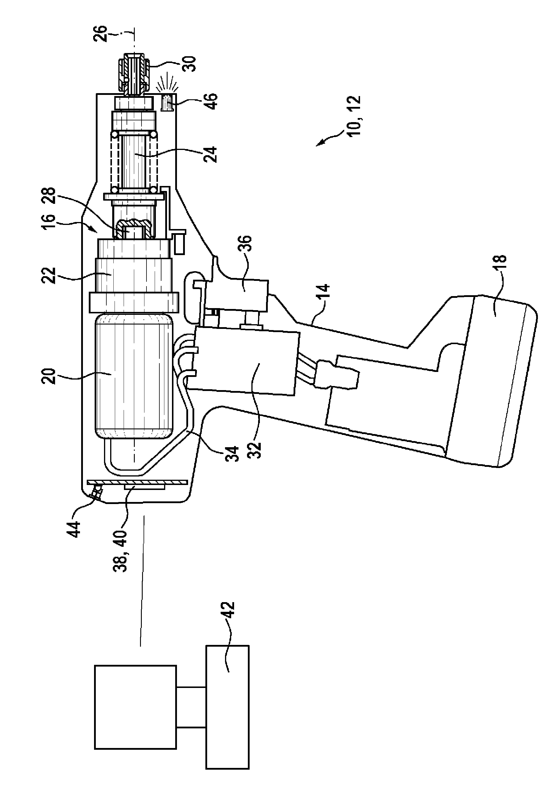
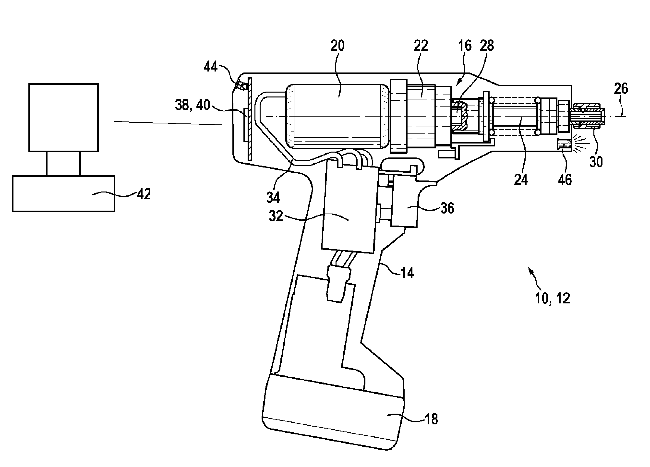
[0028] The drawing shows a hand-held power tool 12 designed as a screwing device 10 . The screwing device 10 is designed in the shape of a pistol and has a housing 14 which is divided into a body part for accommodating a drive 16 and a handle part at its lower end which accommodates a battery module 18 exchangeably. Hand-held power tool 12 is thus designed as a battery-operated electric hand-held power tool, more precisely as an electric drill. The drive 16 of the handheld power tool 12 has an electric motor 20 configured as an electric motor, a downstream transmission 22 and a coupling 24 configured as a disconnect coupling (slip coupling) from which In this respect, the transmission 22 is placed behind.

[0029] Instead of a pistol-shaped configuration of the screwing device 10 , it can also be designed as a stick-shaped screwing device or as an angled screwing device.

[0030] An electric motor 20 configured as an electric motor, a transmission 22 and a coupling 24 are ar...


PUM


Abstract

The invention relates to a hand-held power tool (12), in particular to a screwing device (10), comprising a control device (32) for controlling and / or regulating the tool movement of a tool holder (30) and / or of a tool. According to the invention, the hand-held power tool (12) has an interface (40) for communicating with an external adjustment device (42), said interface (40) being connected to the control device (32), in such a way that signals may be transmitted, for the parameterisation of at least one tool movement sequence comprising a plurality of sequentially-progressing tool movements. The invention also relates to a corresponding method.

Description

technical field [0001] The invention relates to a hand-held power tool, in particular to a screwing device with a control device for controlling and / or adjusting a tool holder and / or a tool movement of the tool. Background technique [0002] Such a handheld power tool is known from DE 2005 056 264 A1 as a screwdriver with a control device for adjusting the rotational speed of the tool receptacle or of the tool accommodated therein. [0003] Such a tightening device is suitable not only for fast screwing in of threaded fasteners, but also for tightening the screwed part with a predetermined torque. As a result of the combination of these properties, a fast screw-in of the threaded fastener at the start of the screw-in and a tightening torque as precise as possible at the end of the screw-in part can be achieved. For this purpose, speed steps different from one another are regulated as a function of the speed, wherein the regulating device uses a value derived from the speed ...

Claims


Application Information

Patent Timeline
Patent Type & Authority Applications(China)
IPC IPC(8): B25B21/00B25B23/14B25B23/147B25F5/00
CPCB25B21/00B25B23/141B25B23/147B25F5/00
Inventor H.瓦内克T.加布里尔
Owner ROBERT BOSCH GMBH
Why Eureka
Try Eureka