
Bearing unit for high rotational speeds

A support unit, high-speed technology, applied in the direction of continuous winding spinning machine, textile and papermaking, open-end spinning machine, etc. The effect of good stability and precision

Inactive Publication Date: 2012-09-12
MASCHINENFABRIK RIETER AG
View PDF11 Cites 0 Cited by
  • Summary
  • Abstract
  • Description
  • Claims
  • Application Information

AI Technical Summary

Problems solved by technology

This is disadvantageous for the load of rolling bearings
In addition, the bending stress of the shaft due to the pressing force of the tangential drive belt is relatively large

Method used


Image

  • Bearing unit for high rotational speeds
  • Bearing unit for high rotational speeds
  • Bearing unit for high rotational speeds

Examples


Embodiment Construction

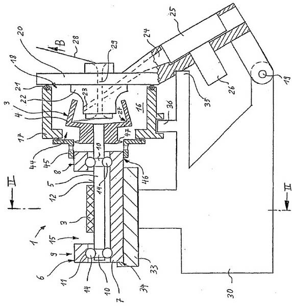
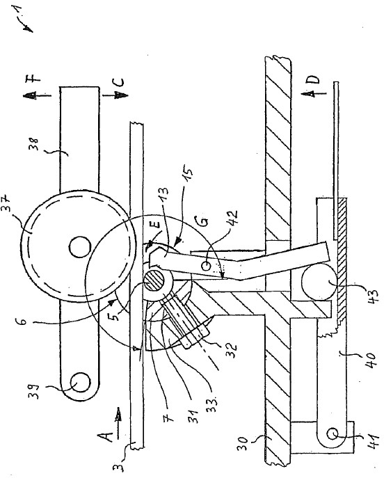
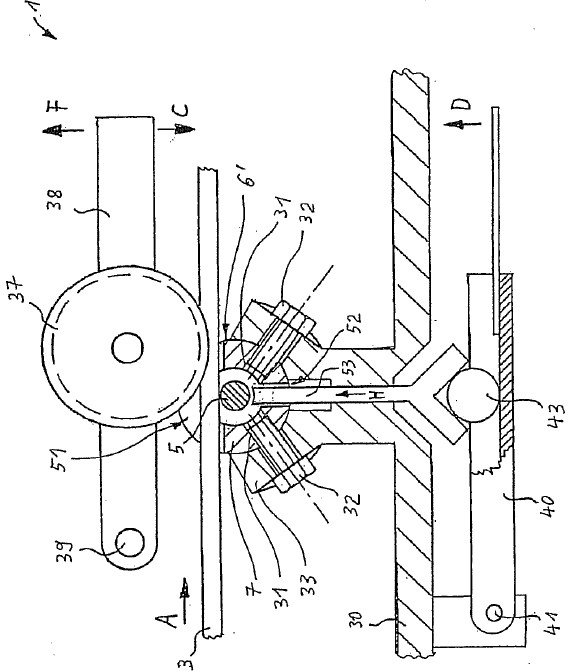
[0017] figure 1 and 2 The open-type textile machine 1 shown in contains a textile machine rotor 2 and a tangential drive belt 3 running in the running direction. The textile machine rotor 2 contains a rotor disk 4 which is mounted on a shaft 5 of a bearing unit 6 . The bearing unit 6 contains a bearing housing 7 in which two rolling bearings 8 and 9 are located. The shaft 5 and the bearing housing 7 each have raceways 10 , 11 for rolling bodies 14 . The bearing housing 7 is designed in the form of a sleeve and directly forms the outer ring for the rolling bearings 8 , 9 via the raceways 11 . The shaft 5 has a surface 12 which forms a running surface for driving the shaft via the tangential drive belt 3 . At the same time, the surface 12 forms a braking surface for braking the shaft by means of the brake pad 13 .

[0018] According to the invention it is provided that the running and braking surfaces 12 are arranged between the two raceways 10 of the rolling bodies 14 . F...


PUM

PropertyMeasurementUnit
Diameteraaaaaaaaaa
Diameteraaaaaaaaaa
Outer diameteraaaaaaaaaa

Abstract

The invention relates to a bearing unit for high rotational speeds, comprising a bearing housing, in which a shaft is arranged that is mounted by means of two rolling bearings. The bearing unit is suitable in particular for a spinning rotor of an open-end spinning device. The shaft and the bearing housing each have raceways for rolling elements. The shaft has a surface that forms a running surface for driving the shaft by means of a tangential belt. The surface of the shaft (5) used as the running surface (12) is arranged between two raceways (10) for rolling elements (14). The bearing housing (7) has at least one opening associated with said surface (12).

Description

technical field [0001] The invention relates to a bearing unit suitable for high rotational speeds, in particular for a textile machine rotor of an open textile machine, which has a bearing housing in which a bearing is supported by means of two rolling bearings. A shaft in which the shaft and the bearing housing have raceways for the rolling elements and in which the shaft has an underside which forms a running surface for driving the shaft by means of a tangential drive belt. Background technique [0002] Bearing units of this type are also referred to as “spherical pivot bearings” and are disclosed, for example, in DE 10 2008 010 366 A1. In known spherical pivot bearings, the shaft protrudes from the bearing housing with two ends. On one of the ends of the shaft, the rotor disk of the rotor of the textile machine is arranged. The other end of the shaft contains the running surface for the tangential drive belt. [0003] Both ends of the shaft must protrude from the bea...

Claims


Application Information

Patent Timeline
IPC IPC(8): D01H4/12
CPCD01H4/12
Inventor W·施特拉泽M·布尔歇特B·洛斯
Owner MASCHINENFABRIK RIETER AG
Learn More