Vehicle control device
A vehicle control device and carrier technology, which can be applied to exhaust devices, mufflers, diagnostic devices of exhaust gas treatment devices, etc., and can solve problems such as undocumented retaining cushions and the like
- Summary
- Abstract
- Description
- Claims
- Application Information
AI Technical Summary
Problems solved by technology
Method used
Image

Examples
no. 1 Embodiment approach ]
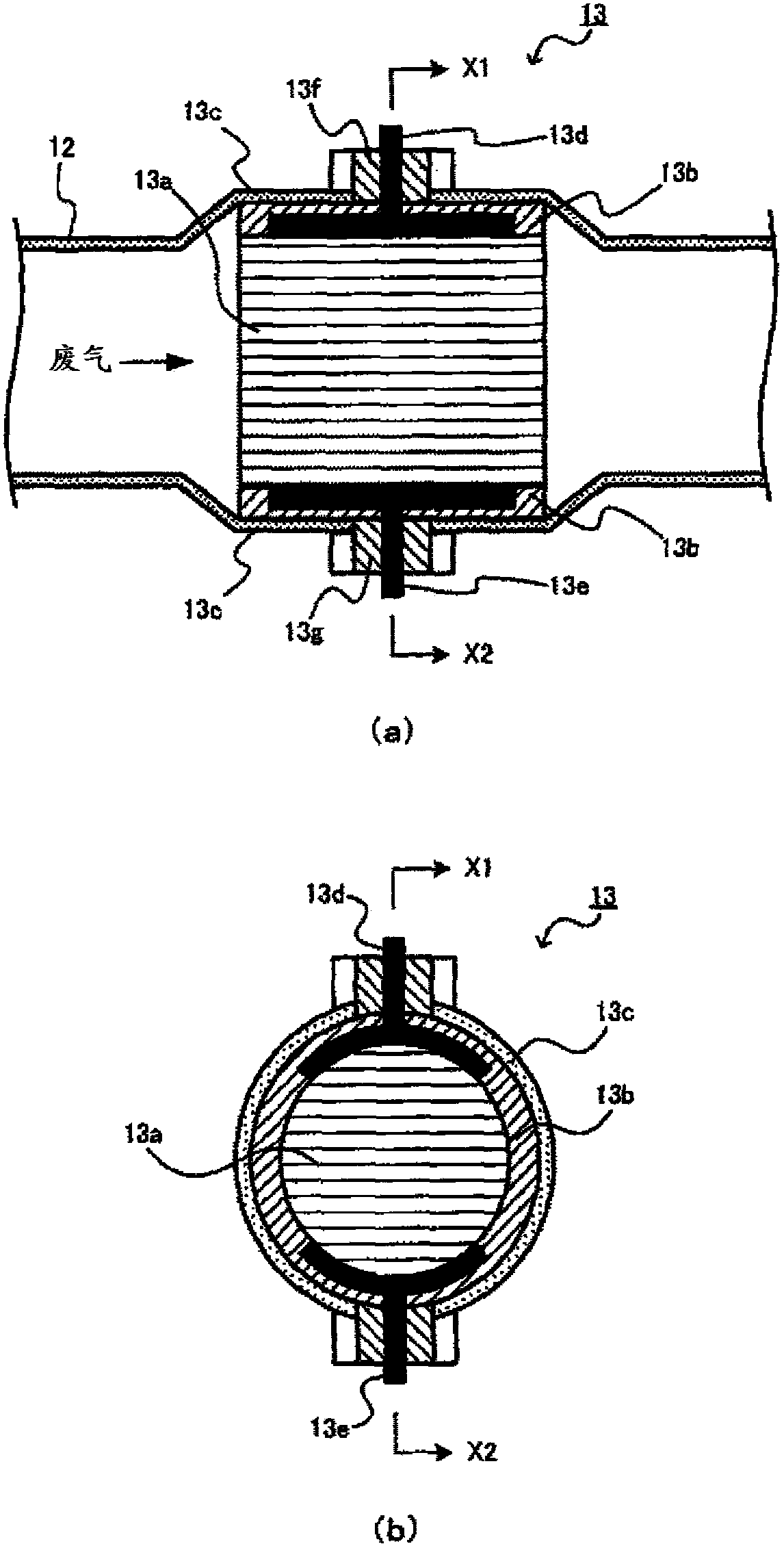
[0081] In the first embodiment, prohibition / permission of energization to the EHC 13 is determined by estimating the insulation resistance of the holding mat 13 b based on the temperature of the holding mat 13 b (hereinafter, appropriately referred to as “holding mat temperature”). This is because the insulation resistance of the holding mat layer 13b tends to change according to the temperature of the holding mat layer. Specifically, in the first embodiment, the ECU 70 determines that the insulation resistance of the holding pad 13b has fallen below a predetermined value when the holding pad temperature is higher than a predetermined temperature, and prohibits energization of the EHC 13 . In this case, ECU 70 does not perform catalyst warm-up by energization even if the EHC energization request is issued.
[0082] refer to Figure 4 and Figure 5 , the reason for controlling the energization of the EHC 13 based on maintaining the pad temperature as described above will be s...
no. 2 Embodiment approach ]
[0120] Next, a second embodiment will be described. In the second embodiment, based on the amount of water absorbed by the holding mat 13b (in other words, the amount corresponding to the exhaust gas condensate held by the holding mat 13b, hereinafter referred to as "mat water absorption" as appropriate.) The point of estimating the insulation resistance of the holding pad layer 13b is different from that of the first embodiment. That is, the second embodiment differs from the first embodiment in that instead of maintaining the mat temperature, prohibition / permission of energization to the EHC 13 is determined based on the mat water absorption amount. Specifically, in the second embodiment, the ECU 70 determines that the insulation resistance of the holding mat 13 b has fallen below a predetermined value when the amount of water absorbed by the mat is greater than or equal to a predetermined value, and prohibits energization of the EHC 13 .
[0121] The reason for controlling...
no. 3 Embodiment approach ]
[0181] Next, a third embodiment will be described. In the third embodiment, in terms of estimating the insulation resistance of the holding pad layer 13b based on the amount of carbon deposited on the holding pad layer 13b (hereinafter, appropriately referred to as "carbon deposition amount"), it is different from the first and the first The second embodiment is different. That is, the third embodiment differs from the first and second embodiments in that the prohibition / permission of energization to the EHC 13 is determined based on the carbon deposition amount instead of maintaining the mat temperature and the mat water absorption amount. Specifically, in the third embodiment, the ECU 70 determines that the insulation resistance of the holding pad layer 13 b has fallen below a predetermined value when the amount of carbon deposition is greater than or equal to a predetermined value, and prohibits energization of the EHC 13 .
[0182] The reason for controlling based on the ...
PUM
 Abstract
Description
Claims
Application Information
 - R&D
- Intellectual Property
- Life Sciences
- Materials
- Tech Scout
- Unparalleled Data Quality
- Higher Quality Content
- 60% Fewer Hallucinations
Browse by: Latest US Patents, China's latest patents, Technical Efficacy Thesaurus, Application Domain, Technology Topic, Popular Technical Reports.
© 2025 PatSnap. All rights reserved.Legal|Privacy policy|Modern Slavery Act Transparency Statement|Sitemap|About US| Contact US: help@patsnap.com