
Hybrid vehicle and method of controlling hybrid vehicle

a hybrid vehicle and hybrid technology, applied in hybrid vehicles, machines/engines, speed sensing governors, etc., can solve the problems of poor drivability and engine not being operated as desired, and achieve the effect of reducing engine torque, reducing engine temperature, and reducing engine torqu

Active Publication Date: 2020-09-17
TOYOTA JIDOSHA KK
View PDF0 Cites 1 Cited by
  • Summary
  • Abstract
  • Description
  • Claims
  • Application Information

AI Technical Summary

Benefits of technology

This patent is about a method for controlling a hybrid vehicle that prevents overheating of the turbo charger and maintains good driving performance. The method involves obtaining the temperature of the turbo charger and setting an operating point on a coordinate plane based on the engine torque and speed. When the temperature reaches a certain threshold, the operating point is adjusted to a lower torque side to prevent excessive engine power demand. The engine and first motor generator are controlled to operate at the set point, while the second motor generator compensates for the shortage of driving force. This method helps to improve the driving experience of the hybrid vehicle while ensuring its optimal performance.

Problems solved by technology

Therefore, depending on a temperature of the component, for protection of the component, the engine may not be operated as desired.
Consequently, the power storage cannot sufficiently be charged or driving force requested of the vehicle cannot be generated, which may lead to poor drivability of the vehicle.

Method used


Image

  • Hybrid vehicle and method of controlling hybrid vehicle
  • Hybrid vehicle and method of controlling hybrid vehicle
  • Hybrid vehicle and method of controlling hybrid vehicle

Examples


first embodiment

As to Drive System of Hybrid Vehicle

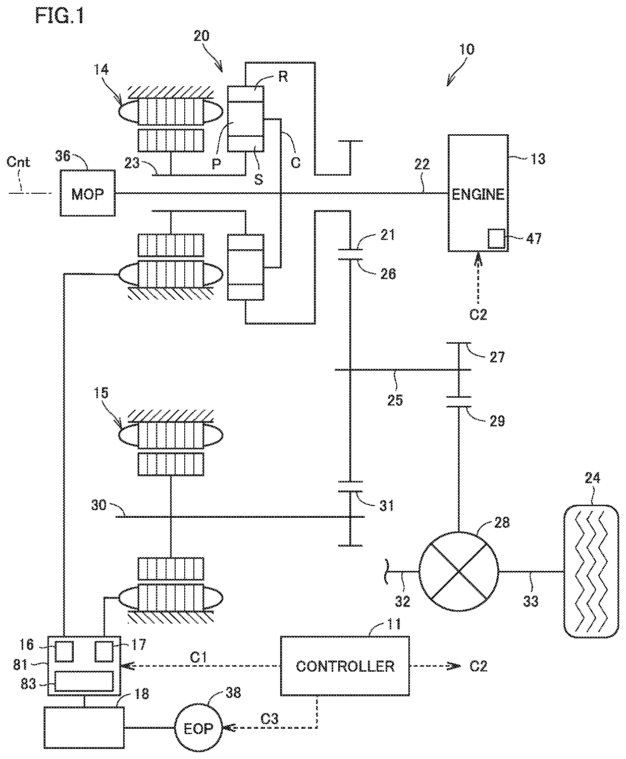
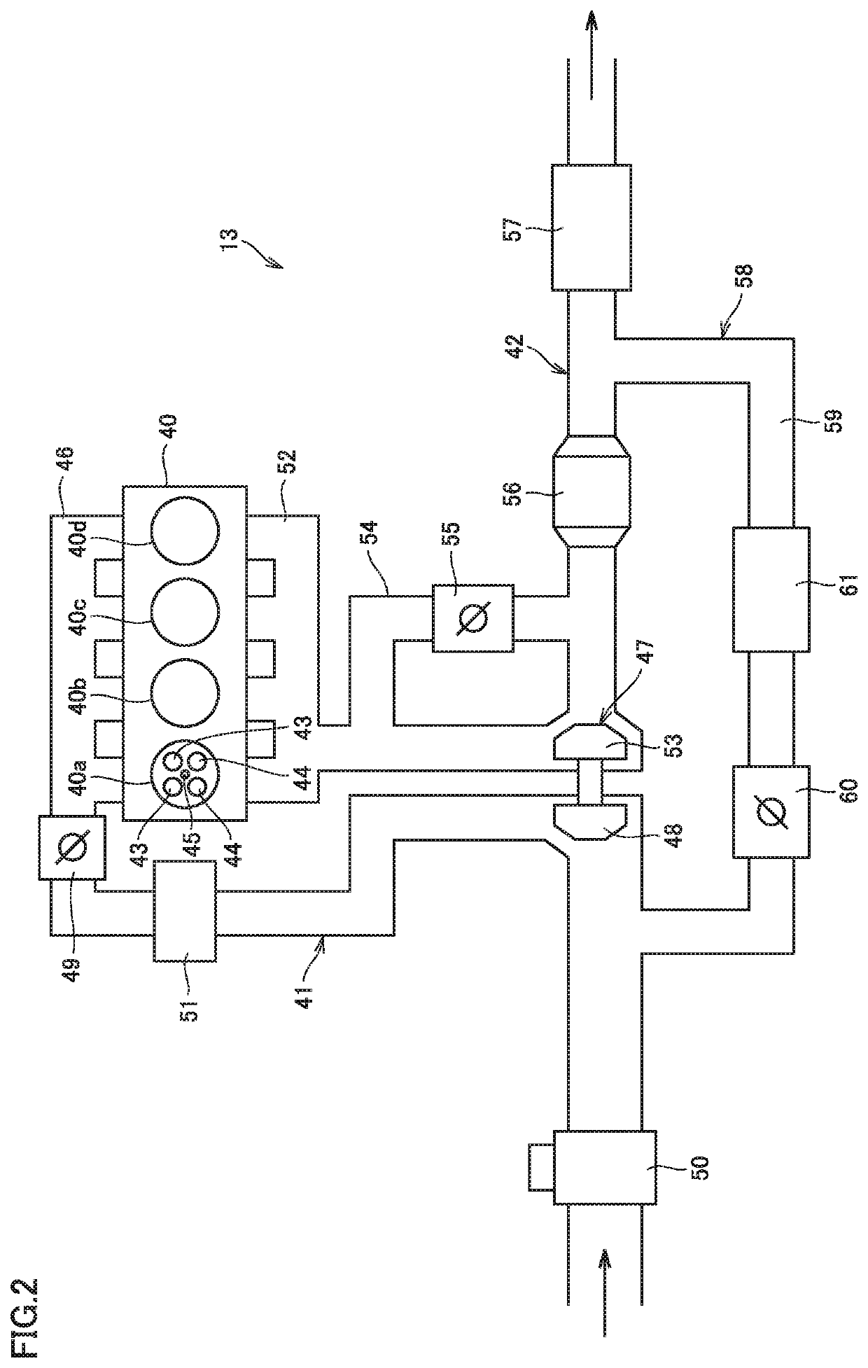
[0028]FIG. 1 is a diagram showing an exemplary configuration of a drive system of a hybrid vehicle (which is simply denoted as a vehicle below) 10. As shown in FIG. 1, vehicle 10 includes as a drive system, a controller 11 as well as an engine 13, a first motor generator (which is denoted as a first MG below) 14, and a second motor generator (which is denoted as a second MG below) 15 that serve as motive power sources for running. Engine 13 includes a turbo charger 47. First MG 14 and second MG 15 each perform a function as a motor that outputs torque by being supplied with driving electric power and a function as a generator that generates electric power by being supplied with torque. An alternating current (AC) rotating electric machine is employed for first MG 14 and second MG 15. The AC rotating electric machine includes, for example, a permanent magnet synchronous motor including a rotor having a permanent magnet embedded.

[0029]First MG 14 an...

second embodiment

[0117]A hybrid vehicle according to a second embodiment will be described below. Vehicle 10 according to the present embodiment is different from vehicle 10 according to the first embodiment described above partially in processing performed by HV-ECU 62. Vehicle 10 according to the present embodiment is otherwise the same in features as vehicle 10 according to the first embodiment described above and those features have the same reference characters allotted. Functions of those features are also the same and therefore detailed description thereof will not be repeated.

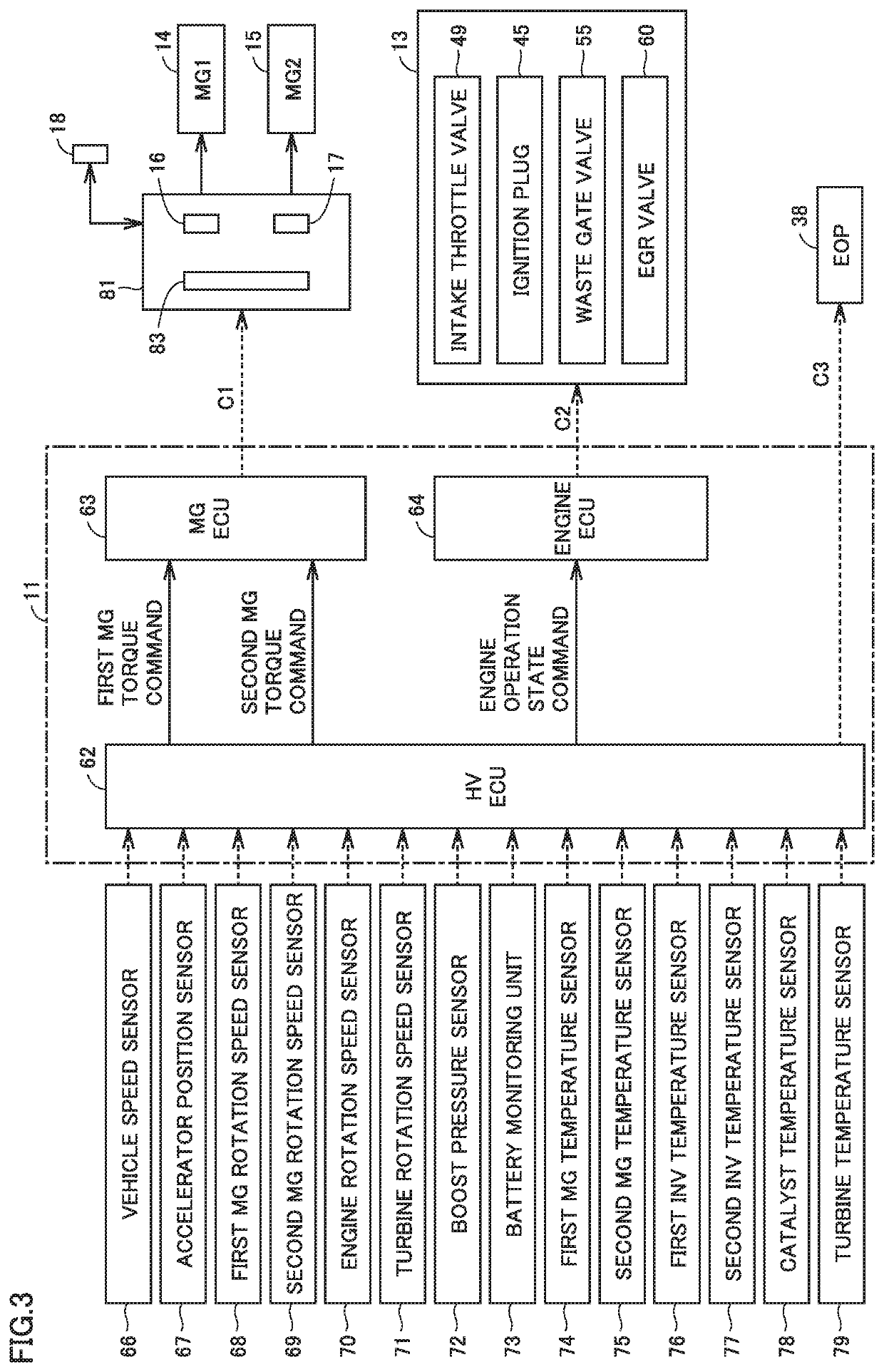
[0118]In the present embodiment, HV-ECU 62 is assumed to operate as below. Specifically, when a turbo temperature does not exceed threshold value Ta, HV-ECU 62 sets as the operating point, a position on the predetermined operating line set on the coordinate plane of engine torque and the engine rotation speed where engine power requested of engine 13 is output. When the turbo temperature exceeds threshold value Ta, HV-E...


PUM


Abstract

An HV-ECU performs processing including calculating requested system power, calculating requested engine power when an engine activation request has been issued, obtaining a turbo temperature, setting an operating point on a predetermined operating line when the turbo temperature is equal to or lower than a threshold value Ta, setting as the operating point, a position on a higher rotation speed side by a predetermined value along an equal power line when the turbo temperature is higher than the threshold value Ta, carrying out engine control, and carrying out MG control.

Description

[0001]This nonprovisional application is based on Japanese Patent Application No. 2019-047180 filed with the Japan Patent Office on Mar. 14, 2019, the entire contents of which are hereby incorporated by reference.BACKGROUNDField[0002]The present disclosure relates to control of a hybrid vehicle incorporating a motor and an engine including a turbo charger as drive sources.Description of the Background Art[0003]A hybrid vehicle that incorporates a motor and an engine as drive sources, includes a power storage charged with motive power of the engine, and runs with motive power of the engine has conventionally been known. Some engines mounted on such a hybrid vehicle include a turbo charger.[0004]For example, Japanese Patent Laying-Open No. 2015-58924 discloses a hybrid vehicle incorporating a motor and an engine including a turbo charger.SUMMARY[0005]In the hybrid vehicle described above, however, a temperature of exhaust increases due to activation of the engine in particular in a hi...

Claims


Application Information

Patent Timeline
Patent Type & Authority Applications(United States)
IPC IPC(8): B60W20/10B60W10/08B60W10/06
CPCB60W10/08B60W2710/0666B60W10/06B60W20/10B60W2710/0677B60W2510/0638F02D29/02F02D29/06F02D31/001B60W20/15F02D2250/18B60K6/445B60W30/1843B60W30/1882B60W2710/083B60W2710/0644Y02T10/72
Inventor YONEZAWA, KOICHIYOSHIZAKI, SATOSHIMAEDA, OSAMUANDO, DAIGOASAMI, YOSHIKAZUITAGAKI, KENJIOYAMA, SHUNSUKEMUTA, KOICHIRO
Owner TOYOTA JIDOSHA KK
Learn More