engine control unit

A control device and engine technology, applied in the direction of engine control, automatic control, automatic control, etc., can solve problems such as deterioration, non-ignition drivability, poor combustion state, etc., and achieve the effect of suppressing the deterioration of drivability

Inactive Publication Date: 2020-06-30
MAZDA MOTOR CORP
View PDF7 Cites 0 Cited by
  • Summary
  • Abstract
  • Description
  • Claims
  • Application Information

AI Technical Summary

Problems solved by technology

[0004] Therefore, it is conceivable to perform AWS control while the vehicle is running, but when the weakly stratified combustion is performed while the vehicle is running like the technology described in Patent Document 1, the desired weakly stratified combustion may not be formed when the operating state of the engine changes. layer state, which produces misfires etc.
On the other hand, it is conceivable to perform homogeneous combustion (combust by forming a homogeneous air-fuel mixture in the combustion chamber) instead of weakly stratified combustion in AWS control. Therefore, when the ignition timing is delayed in homogeneous combustion as in the case of applying weak stratified combustion, misfires and the like may occur and drivability may deteriorate

Method used


Image

  • engine control unit
  • engine control unit
  • engine control unit

Examples


Embodiment Construction

[0033] Hereinafter, an engine control device according to an embodiment of the present invention will be described with reference to the drawings.

[0034]

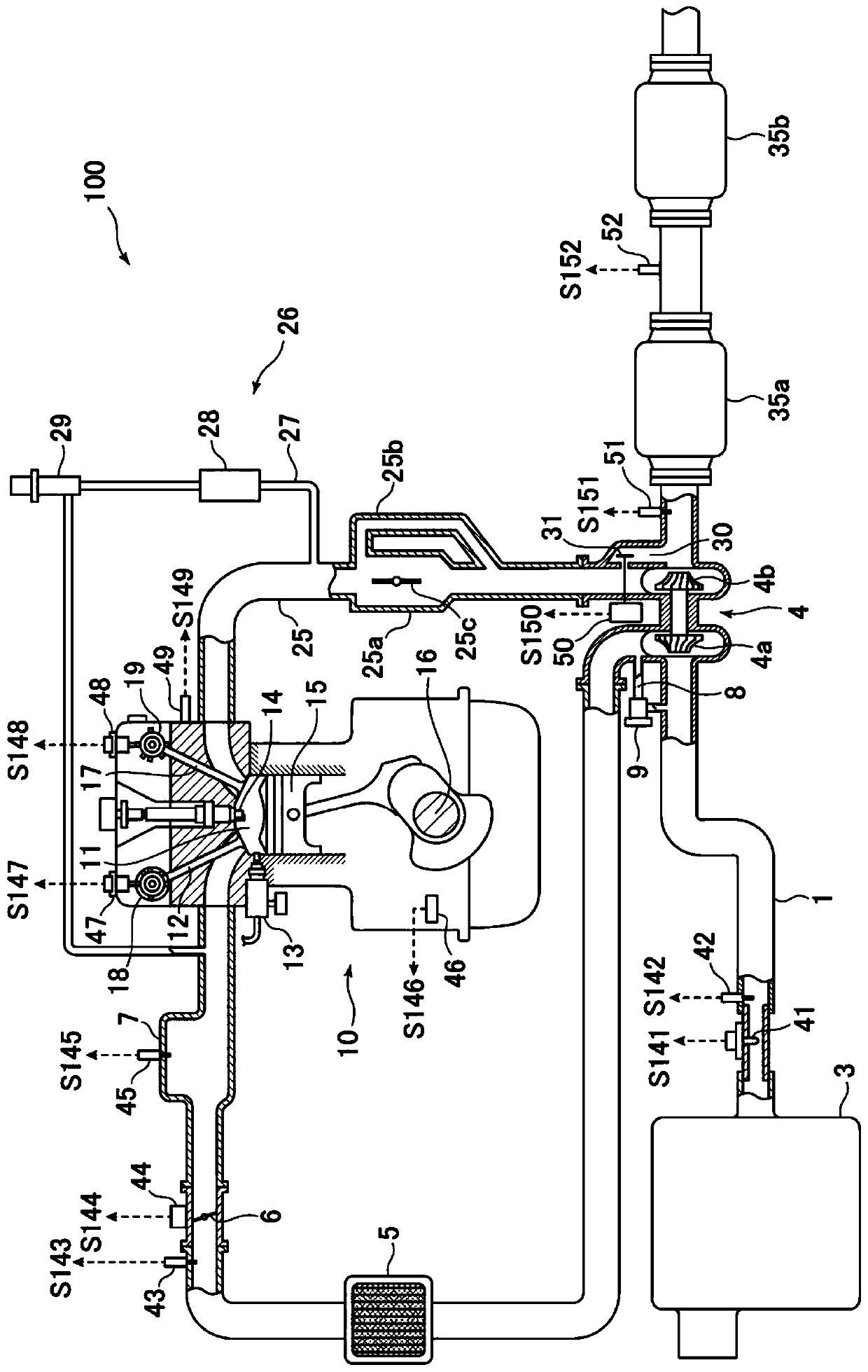
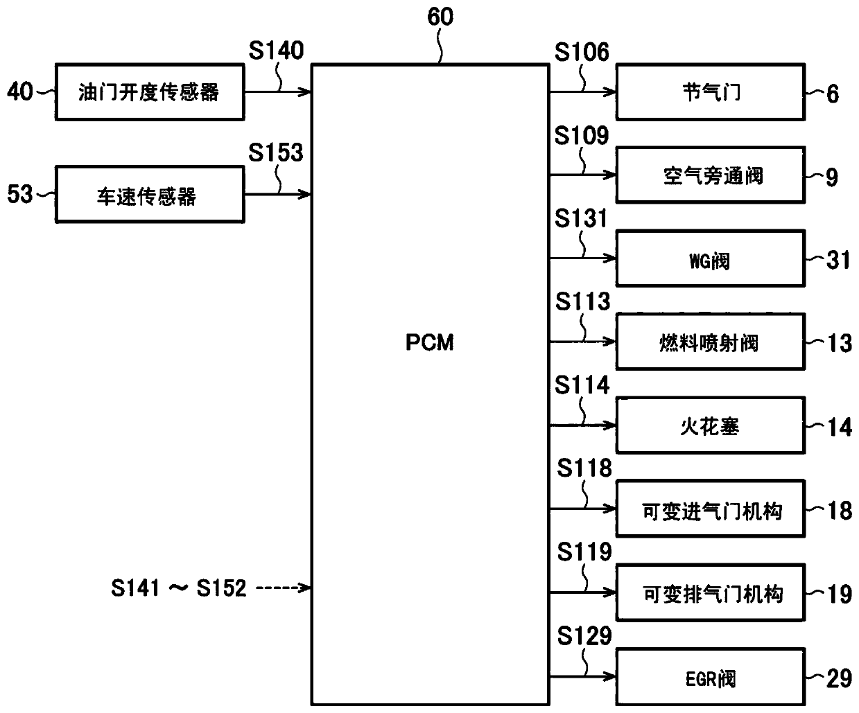
[0035] First, refer to figure 1 as well as figure 2 An engine system to which the engine control device according to the embodiment of the present invention is applied will be described. figure 1 is a schematic configuration diagram of an engine system to which an engine control device according to an embodiment of the present invention is applied, figure 2 It is a block diagram showing the electrical configuration of the engine control device according to the embodiment of the present invention.

[0036] Such as figure 1 as well as figure 2 As shown, the engine system 100 mainly has: an intake passage 1 for passing intake air (air) introduced from the outside; The fuel mixture supplied by the fuel injection valve 13 described later is combusted to generate power for the vehicle; the exhaust passage 25 discharges ...


PUM


Abstract

The invention provides a control device for an engine. While the vehicle is running, the catalyst device is warmed up early by appropriately executing the catalyst early warm-up control while suppressing deterioration of drivability or the like. The PCM (60), which is a control device for the engine, executes the catalyst advance warm-up control (AWS control) as follows when the catalyst device (35) is in an inactive state when the vehicle is running. Fuel injection control for injecting fuel in such a way that a homogeneous air-fuel mixture is formed in the combustion chamber (11) to make it burn homogeneously, and to control the amount of intake air to increase the amount of intake air, and to control the ignition time compared with the reference ignition time. Hysteresis ignition control preheats the catalyst device in advance. In addition, the PCM (60) changes the ignition timing retardation amount by which the ignition timing is retarded from the reference ignition timing by the ignition control according to the engine speed and / or the engine load.

Description

technical field [0001] The present invention relates to an engine control device, and more particularly, to an engine control device for performing early warm-up control on a catalyst device provided in an exhaust passage. Background technique [0002] Conventionally, a technology called AWS (Accelerated Warm-up System: Accelerated Warm-up System) has been implemented in order to realize early activation of a catalyst device provided in an exhaust passage in a spark ignition engine. This AWS is a technology that increases the amount of intake air when the catalyst device is in an inactive state, for example, immediately after a cold start of the engine, compared to when it is in an active state under the same operating state (for example, idling operation). amount, and delay the ignition timing beyond the compression top dead center, so that the mixture gas is post-combusted in the expansion stroke, thereby increasing the temperature of the exhaust gas and increasing the hea...

Claims


Application Information

Patent Timeline
Patent Type & Authority Patents(China)
IPC IPC(8): F02D43/00F01N3/20
CPCF01N3/2006F02D43/00F02D41/068F02D41/3029F02D41/402F02P5/1506F02P5/1508F01N2430/08F01N2900/08F02D2200/501F01N2430/06F02D37/02F02D41/0002F02D41/0255F02D41/3076F02D2200/101F02P5/15Y02A50/20Y02T10/12Y02T10/40F02D41/26F02F3/28
Inventor 上野智弘樋口雄介
Owner MAZDA MOTOR CORP
Why Eureka
Try Eureka