Device and method for controlling a belt-type continuously variable transmission for a vehicle

A continuously variable transmission, control device technology, applied in the direction of elements with teeth, transmission control, belt/chain/gear, etc., can solve problems such as inability to ensure control accuracy, extraction, estimation error, etc.

Inactive Publication Date: 2012-09-12
NISSAN MOTOR CO LTD +1
View PDF5 Cites 11 Cited by
  • Summary
  • Abstract
  • Description
  • Claims
  • Application Information

AI Technical Summary

Problems solved by technology

[0007] However, in the conventional control device of the belt-type continuously variable transmission for vehicles, there is a problem that when the input torque to the belt-type continuously variable transmission mechanism changes rapidly, the change of the secondary oil pressure accompanying the change The speed also becomes faster, and in the actual secondary oil pressure characteristics, it is impossible to clearly extract the excitation-realized vibration components contained in the actual secondary oil pressure from the basic components of the actual secondary oil pressure based on the magnitude of the input torque.
Therefore, when the change speed of the input torque is fast and the vibration component realized by the excitation contained in the actual secondary oil pressure cannot be extracted, when the vibration component realized by the excitation contained in the actual gear ratio and the vibration component contained in the actual secondary oil pressure In belt slip control where the product value of the vibration component achieved by the excitation is an estimated value representing the belt slip state and the value is converged to a specified value, the control accuracy may not be ensured due to the estimation error of the belt slip state. The belt slips greatly in the belt slip control according to the magnitude of the input torque to the belt type continuously variable transmission

Method used


Image

  • Device and method for controlling a belt-type continuously variable transmission for a vehicle
  • Device and method for controlling a belt-type continuously variable transmission for a vehicle
  • Device and method for controlling a belt-type continuously variable transmission for a vehicle

Examples


Embodiment 1)

[0039] First, the configuration will be described.

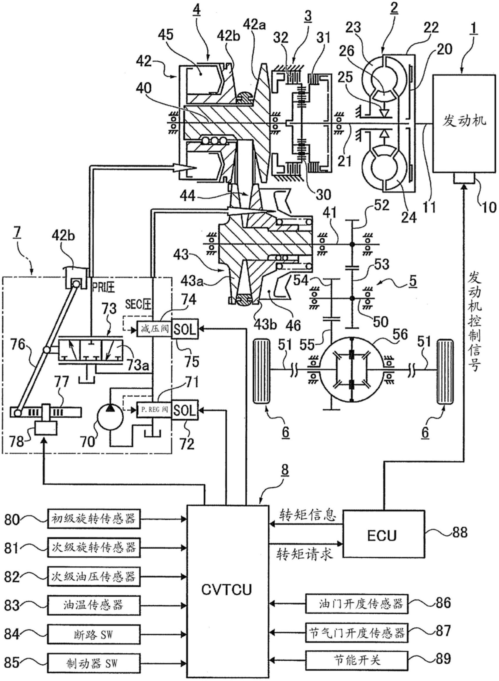
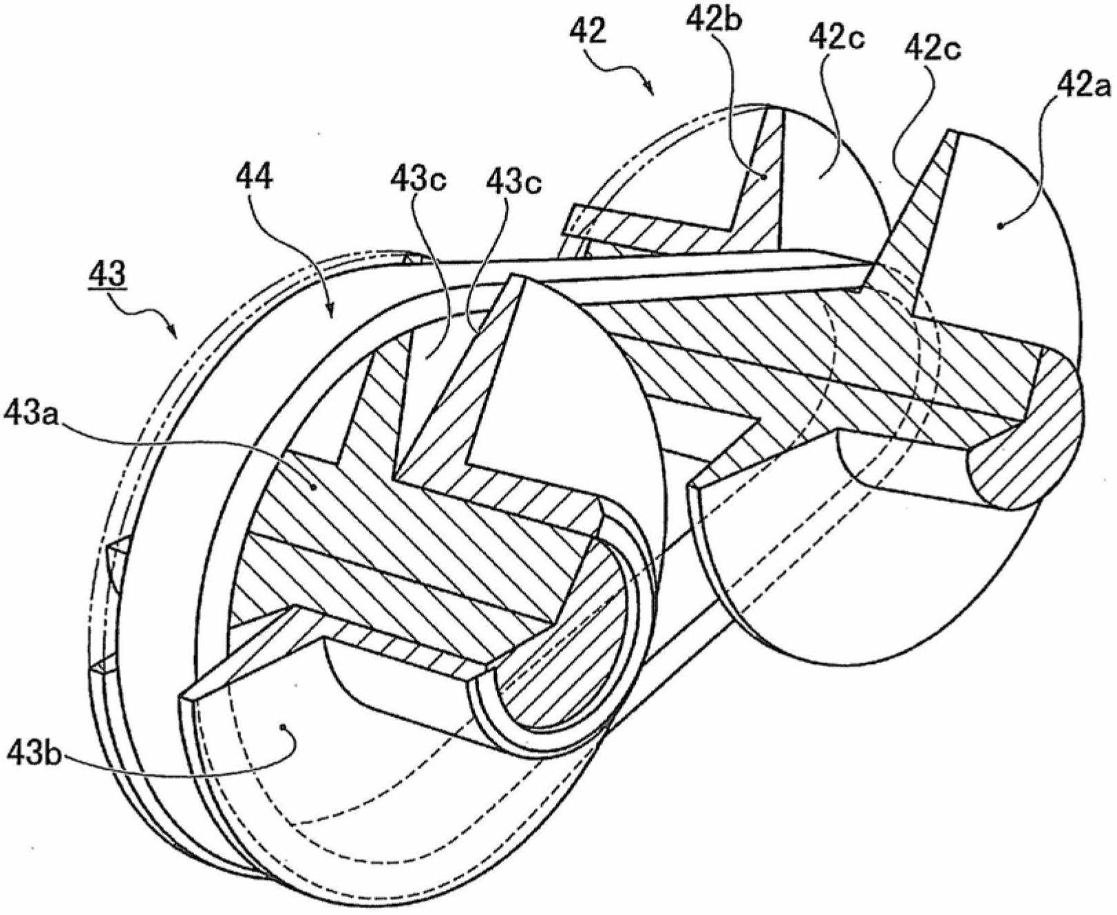
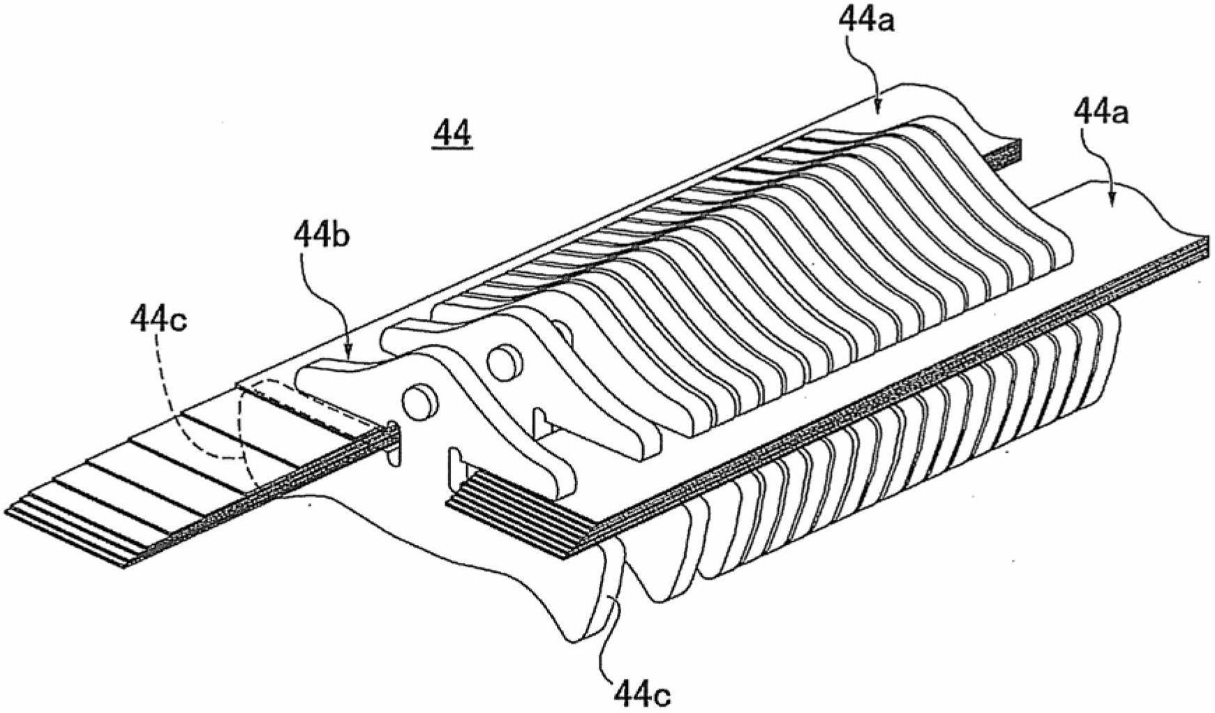
[0040] figure 1 It is an overall system diagram showing a drive system and a control system of a belt-type continuously variable transmission for a vehicle to which the control device and control method of the first embodiment are applied. figure 2 It is a perspective view showing a belt-type continuously variable transmission mechanism to which the control device and control method of the first embodiment are applied. image 3 It is a perspective view of a part of the belt of the belt-type continuously variable transmission mechanism to which the control device and control method of the first embodiment are applied. Below, based on Figure 1 ~ Figure 3 The system configuration will be described.

[0041] Such as figure 1 As shown, the drive system of the belt-type continuously variable transmission for vehicles includes an engine 1, a torque converter 2, a forward-reverse switching mechanism 3, a belt-type continuously...


PUM


Abstract

Disclosed is a continuously variable transmission that expands the operating range over which belt-slip control is allowed, while maintaining the estimated precision of the belt-slip state. This reduces belt friction, thereby reducing the drive energy used. A belt (44) is wrapped around a primary pulley (42) and a secondary pulley (43), and a secondary hydraulic pressure is controlled to produce a belt clamping force in accordance with input torque from an engine (1). The disclosed belt-type continuously variable transmission for a vehicle is provided with a belt-slip control means (fig. 8) and an input-torque change-rate limitation means (step S23 in fig. 12). When the rate of change of the input torque is less than a given value, the belt-slip control means controls the secondary hydraulic pressure on the basis of a phase difference (?) between a vibration component due to oscillation in the actual secondary hydraulic pressure and a vibration component due to oscillation in an actual gear ratio. The input-torque change-rate limitation means uses prescribed acceleration limitation allowance conditions to determine whether or not the acceleration of the vehicle may be limited (steps S21, S22, and S26 in fig. 12), and if so, limits the input-torque change rate to less than the aforementioned given value.

Description

technical field [0001] The present invention relates to a control device and a control method of a belt-type continuously variable transmission for a vehicle, which perform belt slip control in which a belt wound around a pulley slips at a predetermined slip rate. Background technique [0002] Conventionally, as a control device for a belt-type continuously variable transmission for a vehicle, a device is known (for example, refer to Patent Document 1) that makes the actual secondary oil pressure lower than normal control and uses When the belt that is wound around the pulley is slipping at a specified slip rate, the belt slip is controlled. [0003] (a) Superimpose a predetermined sine wave on the secondary oil pressure, that is, excite the secondary oil pressure to make it vibrate, [0004] (b) Based on the product of the excited vibration component included in the actual secondary oil pressure and the excited vibration component included in the actual gear ratio, the sec...

Claims


Application Information

Patent Timeline
Patent Type & Authority Applications(China)
IPC IPC(8): F16H61/02F16H61/662
CPCF16H2059/183F16H63/50F16H61/66272F16H61/02F16H61/662
Inventor 儿玉仁寿吉川泰彰
Owner NISSAN MOTOR CO LTD
Why Eureka
Try Eureka