Branch wire system

A wiring and branching technology, applied in the directions of contacts, electromagnetic relay details, relays, etc., can solve the problems of increased installation area, wiring errors, increased installation area and cost of switchboards, etc., to reduce the number of parts and wiring man-hours , The effect of preventing wiring errors

Inactive Publication Date: 2012-09-12
TOKYO ELECTRON LTD
View PDF7 Cites 2 Cited by
  • Summary
  • Abstract
  • Description
  • Claims
  • Application Information

AI Technical Summary

Problems solved by technology

In the case of a large number of circuit breakers and their subordinate electrical equipment for branching wiring, or in the case of a small size of the distribution board, the work of wiring connection of electric wires is cumbersome.
In addition, wiring is complicated, so wiring errors may occur
[00...

Method used


Image

  • Branch wire system
  • Branch wire system
  • Branch wire system

Examples


Embodiment Construction

[0028] Embodiments of the present invention will be described below with reference to the drawings.

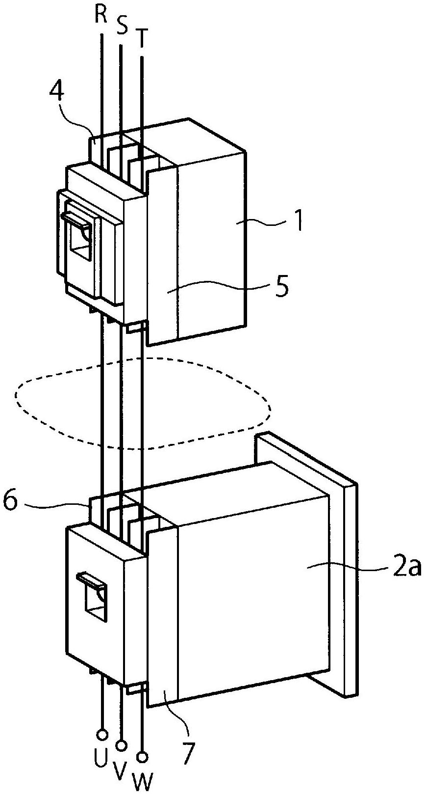
[0029] figure 1 and figure 2 Shows a distribution circuit breaker 1 (hereinafter referred to as "distribution circuit breaker") for branch lines subordinate to a main distribution circuit breaker (not shown) that is fixed in an unshown switchboard in a conventional structure. 1”) and part of the electromagnetic interrupter 2a. The three-phase R, S, T that supplies power to the primary side terminal part 4 of the distribution circuit breaker 1 (MCCB) is connected to the electromagnetic interrupter 2a (MC1) via the secondary side terminal part 5 of the distribution circuit breaker 1 The wires (the part surrounded by the dotted line) of the primary side terminal part 6 separated by phase (R (red), S (white), T (black)) are supplied to the electromagnetic interrupter 2a, and then supplied to the electromagnetic interrupter 2a. To the electrical loads (U, V, W) connected to the...


PUM


Abstract

A molded case circuit breaker (10) has a rear joint surface portion (13), and a first electronic device has a front joint surface portion (21). It is possible to connect the molded case circuit breaker and the first electronic device with each other in the longitudinal direction with the rear joint surface portion and the front joint surface portion in contact with each other. The molded case circuit breaker has an electrically primary side connection terminal portion (30A) for connection to a wiring on the side of a power supply and an electrically secondary side first plug-in terminal portion (30) on the rear joint surface portion. The first electronic device has a first plug terminal portion (22) for connection to the first plug-in terminal portion on the front joint surface portion. The first electronic device has an rear joint surface portion on the side opposite to the front joint surface portion and a second plug-in terminal portion (30B) on the rear joint surface portion. The second plug-in terminal portion is provided at the same position as the first plug terminal portion (22) in terms of the height and the lateral direction.

Description

technical field [0001] The present invention relates to a branch distribution line system provided with electrical equipment such as a circuit breaker for distribution and an electromagnetic interrupter electrically connected thereto. Background technique [0002] Generally, in the electric line on the load side connected to the subordinate part of the three-phase 200V main distribution circuit breaker in the switchboard, the distribution circuit breaker (MCCB: Molded Case Circuit Breaker) and its subordinate The electromagnetic interrupters (Electromagnetic Contact) are arranged in a line, and the secondary side terminals of the wiring circuit breaker and the primary side terminals of the electromagnetic interrupter are connected with wires to supply power to the electrical equipment on the load side. [0003] In Japanese Patent Application Laid-Open No. 7-298426 (document 1) (refer to figure 2 , image 3 , Figure 4 ) discloses that three transition bars connecting a ci...

Claims


Application Information

Patent Timeline
IPC IPC(8): H01H9/02H01H45/14H01H89/00
CPCH01H1/5844H01H1/5866H01H50/14H01H71/08H01H89/06H01H9/02H01H45/14H01H89/00
Inventor 一宫贤治川野利行佐藤尊三
Owner TOKYO ELECTRON LTD
Why Eureka
Try Eureka