Bending machine

A bending machine and hydraulic cylinder technology, applied in the field of bending machines, can solve the problems of wasting manpower, uneven bending, and low efficiency, and achieve the effects of reducing labor, fast bending, and improving efficiency

Inactive Publication Date: 2012-09-19
JIANGYIN DADI EQUIP
View PDF6 Cites 5 Cited by
  • Summary
  • Abstract
  • Description
  • Claims
  • Application Information

AI Technical Summary

Problems solved by technology

[0002]At present, in some countries with limited transportation conditions, it is necessary to bend the fixed-length steel. At pres

Method used


Image

  • Bending machine
  • Bending machine

Examples


Embodiment Construction

[0010] All features disclosed in this specification, or steps in all methods or processes disclosed, may be combined in any manner, except for mutually exclusive features and / or steps.

[0011] Any feature disclosed in this specification (including any appended claims, abstract and drawings), unless expressly stated otherwise, may be replaced by alternative features which are equivalent or serve a similar purpose. That is, unless expressly stated otherwise, each feature is one example only of a series of equivalent or similar features.

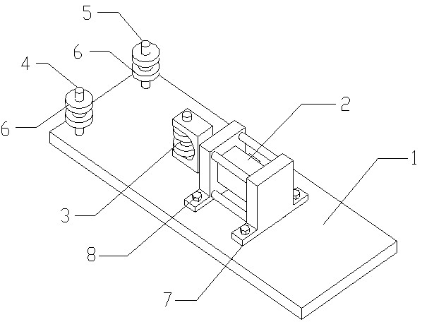
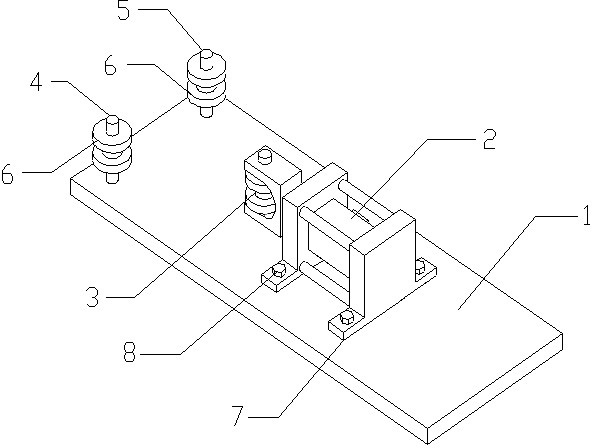
[0012] Depend on figure 1 The shown bending machine includes a base 1, on which a hydraulic cylinder 2 is arranged, and the end of the hydraulic cylinder 2 is provided with a top wheel 3, and the two sides in front of the top wheel 3 are correspondingly provided with a first shaft 4 and the second shaft 5, rollers 6 are arranged symmetrically on the top of the first shaft 4 and the second shaft 5. Two sides of the cylinder body of the hydrau...


PUM


Abstract

The invention discloses a bending machine which comprises a base (1), wherein a hydraulic cylinder (2) is arranged on the base (1); a jacking wheel (3) is arranged on the end part of a stretchable end of the hydraulic cylinder (2); a first shaft (4) and a second shaft (5) are correspondingly arranged on two sides in front of the jacking wheel (3); and rolling wheels (6) are symmetrically arranged on the first shaft (4) and the second shaft (5). The bending machine provided by the invention can reduce manpower, quickly bend and increase efficiency.

Description

technical field [0001] The invention relates to a device for bending steel, especially a bending machine. Background technique [0002] At present, in some countries with limited transportation conditions, it is necessary to bend fixed-length steel materials. At present, the bending is generally done by people. This is a waste of manpower, and the efficiency is not high, and the bending angles are uneven. Contents of the invention [0003] In order to overcome the deficiencies of the prior art, the present invention provides a bending machine. [0004] In order to achieve the above object, the technical solution of the present invention is: a bending machine includes a base, a hydraulic cylinder is provided on the base, a top wheel is provided at the end of the telescopic end of the hydraulic cylinder, and the two sides above the top wheel are correspondingly provided with The first shaft and the second shaft are symmetrically provided with rollers for reducing friction. ...

Claims


Application Information

Patent Timeline
IPC IPC(8): B21D11/00
Inventor 唐瑞刚钱坚强朱洪明颜庆全
Owner JIANGYIN DADI EQUIP
Why Eureka
Try Eureka