A punch for machining the end face of a bearing roller

A technology of end face processing and bearing rollers, which is applied in the field of mechanical processing, can solve the problems of uneven precision and scrapping of bosses, and achieve the effects of prolonging service life, protecting molds from damage, and buffering impact forces

Active Publication Date: 2015-10-14
LUOYANG WEICHUANG BEARING MOLD
View PDF7 Cites 0 Cited by
  • Summary
  • Abstract
  • Description
  • Claims
  • Application Information

AI Technical Summary

Problems solved by technology

[0004] In order to solve the problems of uneven boss precision and scrapping caused by wear and tear in the roller punches produced in the prior art, the present invention provides a punch for processing the end face of bearing rollers. The punch uses a split type to process each The components are then assembled to ensure the uniformity of precision. At the same time, after wear and tear, the components can be adjusted or replaced without replacing the entire mold to restore it to the precision before wear.

Method used


Image

  • A punch for machining the end face of a bearing roller

Examples


Embodiment 1

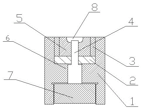
[0022] A punch for machining the end face of a bearing roller, including an outer sleeve 1, a forming core 5, a boss rod 4 and a pressing pad 7, the forming core 5 is embedded in the center hole of the outer sleeve 1, and is formed by the outer sleeve The card platform 6 provided on the inner wall of the barrel 1 is supported, and a forming groove 8 is provided on the outer end surface of the forming core 5. The boss rod 4 is set in the through hole in the center of the forming core 5, and one end thereof is set in the forming groove 8 , and the other end is connected with the pressing pad 7 provided at the end of the outer sleeve 1 .

Embodiment 2

[0024] A punch for machining the end face of a bearing roller, including an outer sleeve 1, a forming core 5, a boss rod 4 and a pressing pad 7, the forming core 5 is embedded in the center hole of the outer sleeve 1, and is formed by the outer sleeve The card platform 6 provided on the inner wall of the barrel 1 is supported, and a forming groove 8 is provided on the outer end surface of the forming core 5. The boss rod 4 is set in the through hole in the center of the forming core 5, and one end thereof is set in the forming groove 8 , the other end is connected with the pressing pad 7 provided at the end of the outer sleeve 1;

[0025] A buffer pad 2 is provided between the forming core 5 and the card table 6;

[0026] In the present invention, the boss rod 4 is composed of two cylinders with different diameters, and the diameter of one end connected to the pressing pad 7 is larger than the diameter of the other end, and the stepped surface at the junction of the two cylind...

Embodiment 3

[0028] A punch for machining the end face of a bearing roller, including an outer sleeve 1, a forming core 5, a boss rod 4 and a pressing pad 7, the forming core 5 is embedded in the center hole of the outer sleeve 1, and is formed by the outer sleeve The card platform 6 provided on the inner wall of the barrel 1 is supported, and a forming groove 8 is provided on the outer end surface of the forming core 5. The boss rod 4 is set in the through hole in the center of the forming core 5, and one end thereof is set in the forming groove 8 , the other end is connected with the pressing pad 7 provided at the end of the outer sleeve 1;

[0029] An annular prestressed sleeve 3 is provided between the forming core 5 and the inner wall of the outer sleeve 1;

[0030] A buffer pad 2 is provided between the forming core 5 and the card table 6;

[0031] In the present invention, the boss rod 4 is composed of two cylinders with different diameters, and the diameter of one end connected to...


PUM


Abstract

A punch for processing a bearing roller end surface comprises an outer sleeve, a moulding core, a boss rod, a pressing pad, a prestressing sleeve and a cushion pad, wherein the moulding core is embedded into a central hole of the outer sleeve and is supported by a clamping table arranged on the inner wall of the outer sleeve; the boss rod is inserted into a through hole in the center of the moulding core; the other end of the boss rod is connected with the pressing pad arranged on the end part of the outer sleeve; the annular prestressing sleeve is arranged between the moulding core and the inner wall of the outer sleeve; and the cushion pad is arranged between the moulding core and the clamping table. The punch for processing the bearing roller end surface is separated into the moulding core and the boss rod of which the position can be regulated, and after the boss rod is abraded, the position of the boss rod is regulated by the pressing pad or the boss rod is changed so as to return the state of the boss rod to an initial state, so that the punch can keep a high-precision state all the time; and the prestressing sleeve and the cushion pad are arranged, so that impact on the punch is buffered and the service life of the punch is prolonged.

Description

technical field [0001] The invention relates to the field of machining, in particular to a punch used for machining the end face of a bearing roller. Background technique [0002] As a kind of bearing, roller bearings are widely used in various large machinery, vehicles and other fields. In the prior art, the rollers in roller bearings are produced by stamping method. First, the materials are made into stamping dies, dies The shape of the roller matches the shape of the roller to be processed, and then the punch and die are used to extrude the material into a predetermined shape. [0003] The roller punch in the prior art has an integrated structure, that is, the material is processed into a mold by lathe, grinding and other processes, and then the roller is produced by stamping. However, due to the accuracy and life of the processing, the produced There is a deviation in the precision of the mold, which leads to the precision of the roller produced by the stamping method b...

Claims


Application Information

Patent Timeline
Patent Type & Authority Patents(China)
IPC IPC(8): B21D37/00B21D53/10
Inventor 张亚纳赵宁义
Owner LUOYANG WEICHUANG BEARING MOLD
Why Eureka
Try Eureka