Multi-functional multi-specification combined tool set

A combined tool and multi-specification technology, applied in the field of hardware tools, can solve the problems of single angle of lighting, inconvenience, and large size of the lighting lamp, and achieve the effect of compact structure and ingenious design.

Inactive Publication Date: 2012-09-19
新昌县兄弟工具有限公司
View PDF8 Cites 2 Cited by
  • Summary
  • Abstract
  • Description
  • Claims
  • Application Information

AI Technical Summary

Problems solved by technology

[0002] For reasons such as work convenience and easy portability, some frequently used hardware tool heads are inserted into a box, and then a common sleeve is equipped for these hardware tools, and when the work requires The hardware tool head is pulled out and inserted into the sleeve for use. In order to prevent the tool head from running when carrying it, the hardware tool head is inserted in the box very firmly, so it will be very laborious to pull out the hardware tool head. Not to mention that the hands will sweat during the work, which will slip when pulling out the hardware tool head and cause the hardware tool head to be unplugged. At the same time, for the convenience of taking and placing, there is a relatively large gap between the hardware tool heads , which makes a lot of space occupied by multiple hardware tool heads
[0003] When working in many dimly lit conditions, lighting tools such as flashlights are used for lighting. In this way, one hand holds the flashlight and the other hand performs the operation of opening the fastener. It takes a lot of force to tighten the fasteners. Generally, one hand needs to hold the object while the other operates. If one hand holds a flashlight for lighting, it will be very difficult to operate with only one hand. Inconvenient, there is also a lighting lamp fixed on the hardware tool in order to solve the lighting problem during the operation, but such a lighting lamp is bulky and cannot be closely matched with the hardware tool, and the lighting angle is single and can only illuminate straight ahead in this direction

Method used


Image

  • Multi-functional multi-specification combined tool set
  • Multi-functional multi-specification combined tool set
  • Multi-functional multi-specification combined tool set

Examples


Embodiment

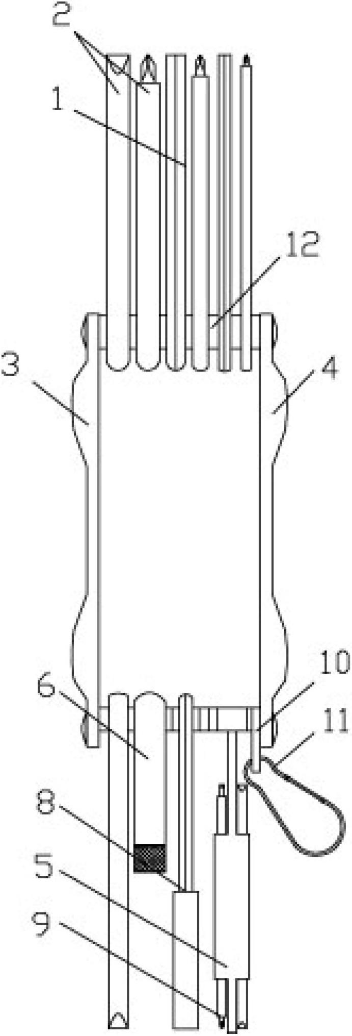
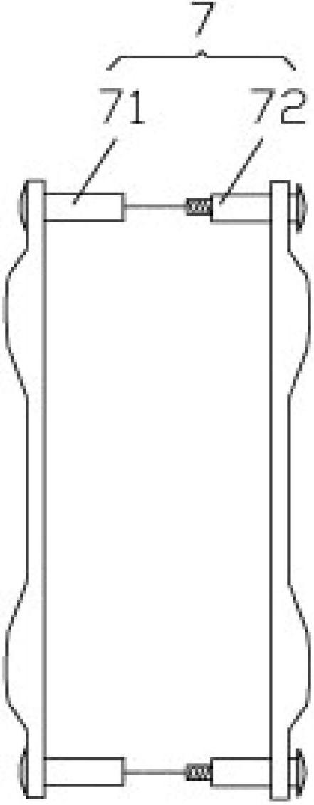
[0028] Example: see Figures 1 to 11 , a multi-functional and multi-standard set combination tool, including several different specifications of screwdrivers 2 or hexagonal rod cone 1, left combined plate frame 3, right combined plate frame 4 and docking shaft 7, the docking shaft 7 is made of belt The left butt joint shaft 71 and the right butt joint shaft 72 of the top of the hat are screwed together to form, and two left butt joint shafts 71 and two right butt joint shafts 72 are inserted and sleeved respectively on the left combined pallet 3 and the right combined pallet 4. in the hole;

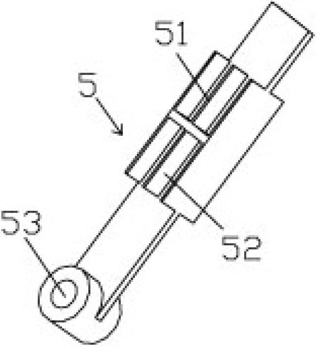
[0029] Screwdriver 2 or hexagonal rod cone 1, combined sleeve 8 and combined tool receiving seat 5 are hinged on the docking shaft 7, and several elastic partitions 51 are formed on the combined tool receiving seat 5, and each two elastic partitions 51 Form a receiving card slot 52 between them, and the combination tool head 9 is elastically clamped in the receiving card slot 52. The com...


PUM


Abstract

The invention discloses a multi-functional multi-specification combined tool set which comprises a plurality of screw drivers or inner hexagonal rod cones, a left combined plate rack, a right combined plate rack and a butt joint shaft, wherein the butt joint shaft consists of left butt joint shafts and right butt joint shafts which are provided with crowns and are in threaded connection; the two left butt joint shafts and the two right butt joint shafts are respectively inserted and sleeved in preset holes of the left combined plate rack and the right combined plate rack; the screw drivers or the inner hexagonal rod cones, a combined sleeve and a combined tool containing seat are articulated with the butt joint shaft; a plurality of elastic baffle plates are molded on the combined tool containing seat; a containing clamping groove is formed between every two elastic baffle plates; combined tool heads are elastically clamped in the containing clamping grooves, the tool heads are more convenient to take and put, all the tool heads are arranged more compactly, and a great amount of tool heads can be contained only in a very small space.

Description

Technical field: [0001] The invention relates to the technical field of hardware tools, and more specifically relates to a combination tool which sets hardware tools of various specifications together. Background technique: [0002] For reasons such as work convenience and easy portability, some frequently used hardware tool heads are inserted into a box, and then a common sleeve is equipped for these hardware tools, and when the work requires The hardware tool head is pulled out and inserted into the sleeve for use. In order to prevent the tool head from running when carrying it, the hardware tool head is inserted in the box very firmly, so it will be very laborious to pull out the hardware tool head. Not to mention that the hands will sweat during the work, which will slip when pulling out the hardware tool head and cause the hardware tool head to be unplugged. At the same time, for the convenience of taking and placing, there is a relatively large gap between the hardware...

Claims


Application Information

Patent Timeline
Patent Type & Authority Applications(China)
IPC IPC(8): B25F1/02
Inventor 刘红标
Owner 新昌县兄弟工具有限公司
Why Eureka
Try Eureka