Thermal system with double reheat
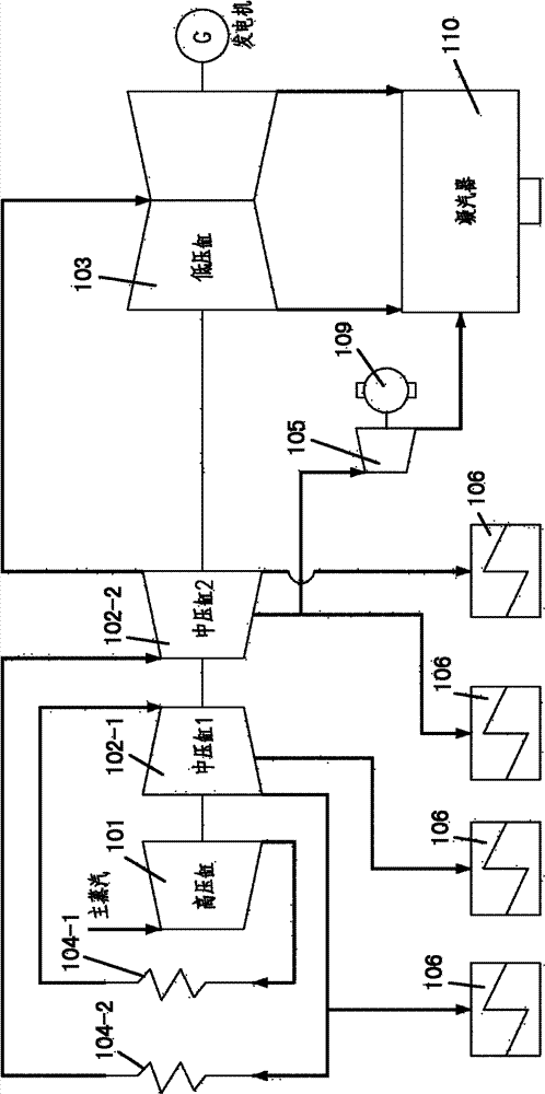
A technology of thermal system and secondary reheating, which is applied in the direction of steam engine device, steam application, machine/engine, etc., and can solve the problems of high superheat, high superheat of extraction steam, affecting thermal cycle efficiency, etc.
- Summary
- Abstract
- Description
- Claims
- Application Information
AI Technical Summary
Problems solved by technology
Method used
Image
Examples
no. 1 example
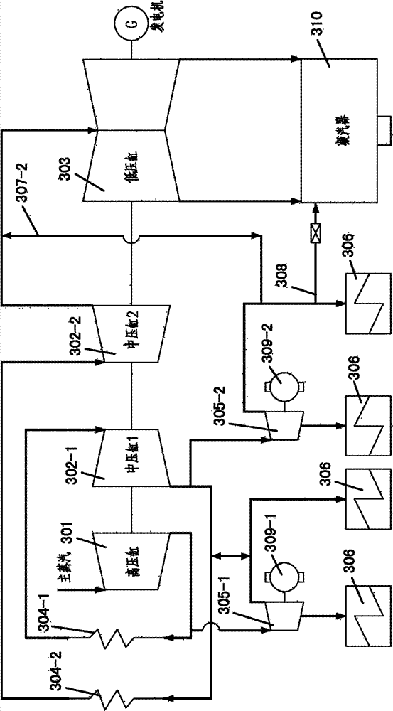
[0034] image 3 A schematic structure of a double reheat thermal system of a preferred embodiment of the present invention is shown. Such as image 3 As shown, the thermal system for secondary reheating of the present invention mainly includes: a high-pressure cylinder 301, a first medium-pressure cylinder 302-1, a second medium-pressure cylinder 302-2, a low-pressure cylinder 303, a first reheater 304-1, The second reheater 304-2, the first small back-pressure steam extraction machine 305-1, the second small back-pressure steam extraction machine 305-2, and multiple heat recovery devices 306.
[0035] In the figure, the high-pressure cylinder 301, the first medium-pressure cylinder 302-1, the second medium-pressure cylinder 302-2 and the low-pressure cylinder 303 are connected in sequence. The main steam passes through the high-pressure cylinder 301, and the steam reheated by the first reheater 304-1 arranged between the high-pressure cylinder 301 and the first medium-press...
no. 2 example
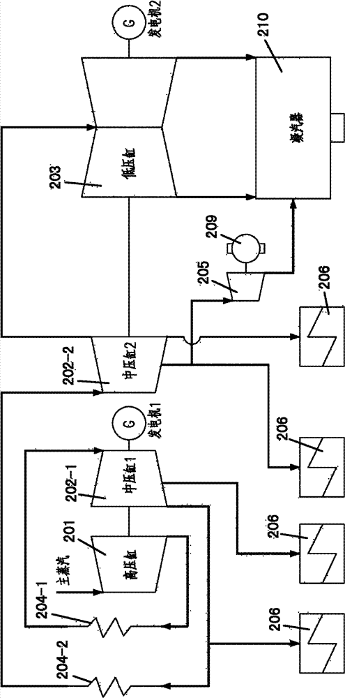
[0043] Figure 4 Another preferred embodiment of the invention is shown. especially, Figure 4 The example shown with the image 3 The same part can directly follow the description in the first embodiment above, and will not be repeated here. In addition, unless otherwise specified in the manual, Figure 4 The reference numerals in the image 3 in the same order. E.g, Figure 4 The index 401 in the image 3 Reference number 301 in indicates the same device or equipment. In the figure, the heat recovery equipment can be a single-row 100% capacity heater, and the heater can also adopt a double-row 50% capacity type.
[0044] and image 3 the difference is, Figure 4 The steam turbine generator set of the shown embodiment is a double-shaft type, and different steam turbines drive two generators on separate shafts, namely Figure 4 Generator 1 and Generator 2 in image 3 In the shown embodiment, the steam turbine generator set is a single-shaft type, and each steam tur...
no. 3 example
[0046] Figure 5 Another preferred embodiment of the invention is shown. especially, Figure 5 The example shown with the image 3 The same part can directly follow the description in the first embodiment above, and will not be repeated here. In addition, unless otherwise specified in the manual, Figure 5 The reference numerals in the image 3 in the same order. E.g, Figure 5 The reference number 501 in the image 3 Reference number 301 in indicates the same device or equipment.
[0047] and image 3 the difference is, Figure 5 The two-stage back-pressure steam extraction small machine of the shown embodiment coaxially drives the same equipment, namely Figure 5 in the driven device 509-2; and in image 3 In the shown embodiment, the 2-stage back-pressure steam extraction small machine drives different devices asynchronously, namely image 3 The driven devices 309-1 and 309-2 in.
PUM
 Abstract
Description
Claims
Application Information
 - R&D Engineer
- R&D Manager
- IP Professional
- Industry Leading Data Capabilities
- Powerful AI technology
- Patent DNA Extraction
Browse by: Latest US Patents, China's latest patents, Technical Efficacy Thesaurus, Application Domain, Technology Topic, Popular Technical Reports.
© 2024 PatSnap. All rights reserved.Legal|Privacy policy|Modern Slavery Act Transparency Statement|Sitemap|About US| Contact US: help@patsnap.com


