
Reciprocating material feeding type high-concentration dust producer

A reciprocating feeding and high-concentration technology, which is applied in the fields of instruments, scientific instruments, suspensions and porous materials analysis, etc., can solve the problem of small amount of dust generated by the dust generator, which cannot truly reflect the performance of the equipment, and cannot scientifically judge the performance of the dust removal equipment, etc. problems, to achieve the effect of scientific and reasonable dust suppression efficiency inspection and detection, compact structure and reliable use

Active Publication Date: 2012-09-19
CHINA COAL TECH ENG GRP CHONGQING RES INST
View PDF6 Cites 3 Cited by
  • Summary
  • Abstract
  • Description
  • Claims
  • Application Information

AI Technical Summary

Problems solved by technology

[0002] As the country attaches great importance to dust control, many environmental management units have successively developed a variety of large air volume dust removal equipment with different specifications and models. The small amount of dust generation (12g / min) cannot meet the requirements of the inspection standard, and the inspection department can only detect it through manual dust generation, but human operation errors bring many uncertain factors to the detection of dust removal equipment, resulting in the test data Distortion cannot truly reflect the performance of the tested equipment at all, and cannot scientifically judge the performance of its dust removal equipment

Method used


Image

  • Reciprocating material feeding type high-concentration dust producer
  • Reciprocating material feeding type high-concentration dust producer
  • Reciprocating material feeding type high-concentration dust producer

Examples


Embodiment Construction

[0026] Below in conjunction with accompanying drawing and embodiment the present invention will be further described:

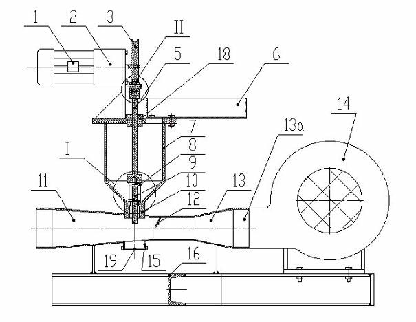
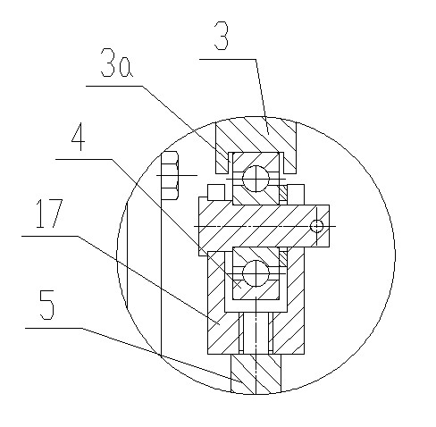
[0027] Such as figure 1 , figure 2 and image 3 As shown, a reciprocating feed type high-concentration dust generator includes a launch tube 11 and an air-inducing tube 13, the air inlet 13a of the air-inducing tube 13 is connected to the blower 14, and the launch tube 11, the air-inducing tube 13 and the blower are connected to the frame 16 fixed connections.

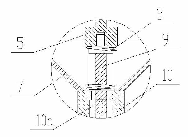
[0028] A shaft sleeve 10 is arranged radially above the emitting tube 11 , and a dust generating rod 9 is arranged inside the shaft sleeve 10 . The inner hole 10a of the shaft sleeve 10 is a stepped hole, and the diameter of the lower end of the stepped hole is larger than that of the upper end. The diameter of the dust generating rod 9 is smaller than the minimum diameter of the inner hole 10a of the shaft sleeve 10 . The size of the dust-generating rod can be selected according to the air volu...


PUM


Abstract

The invention discloses a reciprocating material feeding type high-concentration dust producer which comprises a launching barrel and an air drafting baffle. The launching barrel and the air drafting baffle are connected with a rack fixedly; a shaft sleeve is arranged above the launching barrel along the radial direction; a dust producing rod is arranged in the shaft sleeve; the diameter of the dust producing rod is smaller than the aperture of the inner hole of the shaft sleeve; a reciprocating motion rod is fixedly connected at the upper end of the dust producing rod; a dust depositing tank is arranged above the shaft sleeve; the upper end of the reciprocating motion rod penetrates through the dust depositing tank; the lower end of the reciprocating motion rod is located in the dust depositing tank; the dust depositing tank is communicated with the launching barrel through the shaft sleeve; a bearing installation base is fixed at the upper end of the reciprocating motion rod; a rolling bearing is arranged in the bearing installation base; the rolling bearing is in rolling contact with an eccentric wheel; the eccentric wheel is connected with a speed change device; the speed change device is connected with a motor; a spring is arranged between the reciprocating motion rod and the shaft sleeve; and the air drafting barrel is provided with an original dust gauge opening under the shaft sleeve. The dust producer is in a manner of reciprocating material feeding with large dust production quantity, high dust production concentration and small dust production error.

Description

technical field [0001] The invention relates to a dust generator for testing the dust removal efficiency of the dust collector. Background technique [0002] As the country attaches great importance to dust control, many environmental management units have successively developed a variety of large air volume dust removal equipment with different specifications and models. The small amount of dust generation (12g / min) cannot meet the requirements of the inspection standard, and the inspection department can only detect it through manual dust generation, but human operation errors bring many uncertain factors to the detection of dust removal equipment, resulting in the test data The distortion cannot truly reflect the performance of the tested equipment at all, and cannot make a scientific judgment on the performance of the dust removal equipment. [0003] Therefore those skilled in the art devote themselves to developing a kind of high-concentration dust generator. Content...

Claims


Application Information

Patent Timeline
IPC IPC(8): G01M99/00G01N15/06
Inventor 张少华李德文隋金君黄金星张小涛包亮王军张平黄立宁颜鸽来严春
Owner CHINA COAL TECH ENG GRP CHONGQING RES INST
Learn More