
Super-fluorescence optical fiber light source and method for generating super-fluorescence

A fiber light source and production method technology, applied in lasers, laser parts, semiconductor lasers, etc., to achieve high average wavelength stability, high flexibility, and the effect of reducing pump wavelength and pump power

Active Publication Date: 2014-04-09
TSINGHUA UNIV
View PDF4 Cites 0 Cited by
  • Summary
  • Abstract
  • Description
  • Claims
  • Application Information

AI Technical Summary

Problems solved by technology

[0004] The purpose of the present invention is to at least solve one of the above-mentioned technical defects, especially to reduce the impact of ambient temperature changes on LD pump power and pump wavelength, and to solve the need for strict temperature control of LD pump sources in existing superfluorescent optical fiber light sources. deficiencies in control

Method used


Image

  • Super-fluorescence optical fiber light source and method for generating super-fluorescence
  • Super-fluorescence optical fiber light source and method for generating super-fluorescence

Examples


Embodiment Construction

[0027] Embodiments of the present invention are described in detail below, examples of which are shown in the drawings, wherein the same or similar reference numerals designate the same or similar elements or elements having the same or similar functions throughout. The embodiments described below by referring to the figures are exemplary only for explaining the present invention and should not be construed as limiting the present invention.

[0028] In describing the present invention, it should be understood that the terms "center", "longitudinal", "transverse", "upper", "lower", "front", "rear", "left", "right", " The orientations or positional relationships indicated by "vertical", "horizontal", "top", "bottom", "inner", "outer", etc. are based on the orientation or positional relationships shown in the drawings, and are only for the convenience of describing the present invention and simplifying Describes, but does not indicate or imply that the device or element referred...


PUM


Abstract

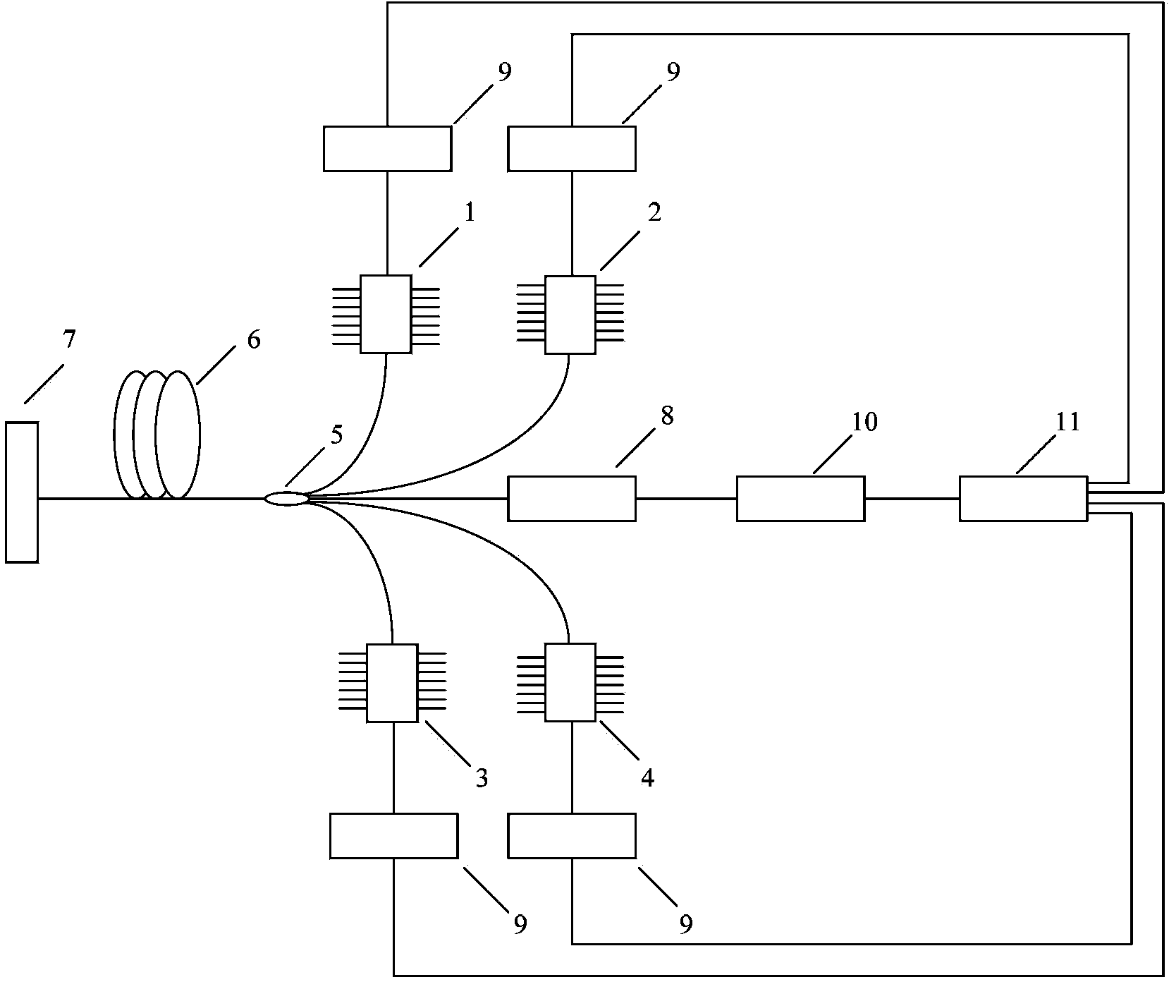
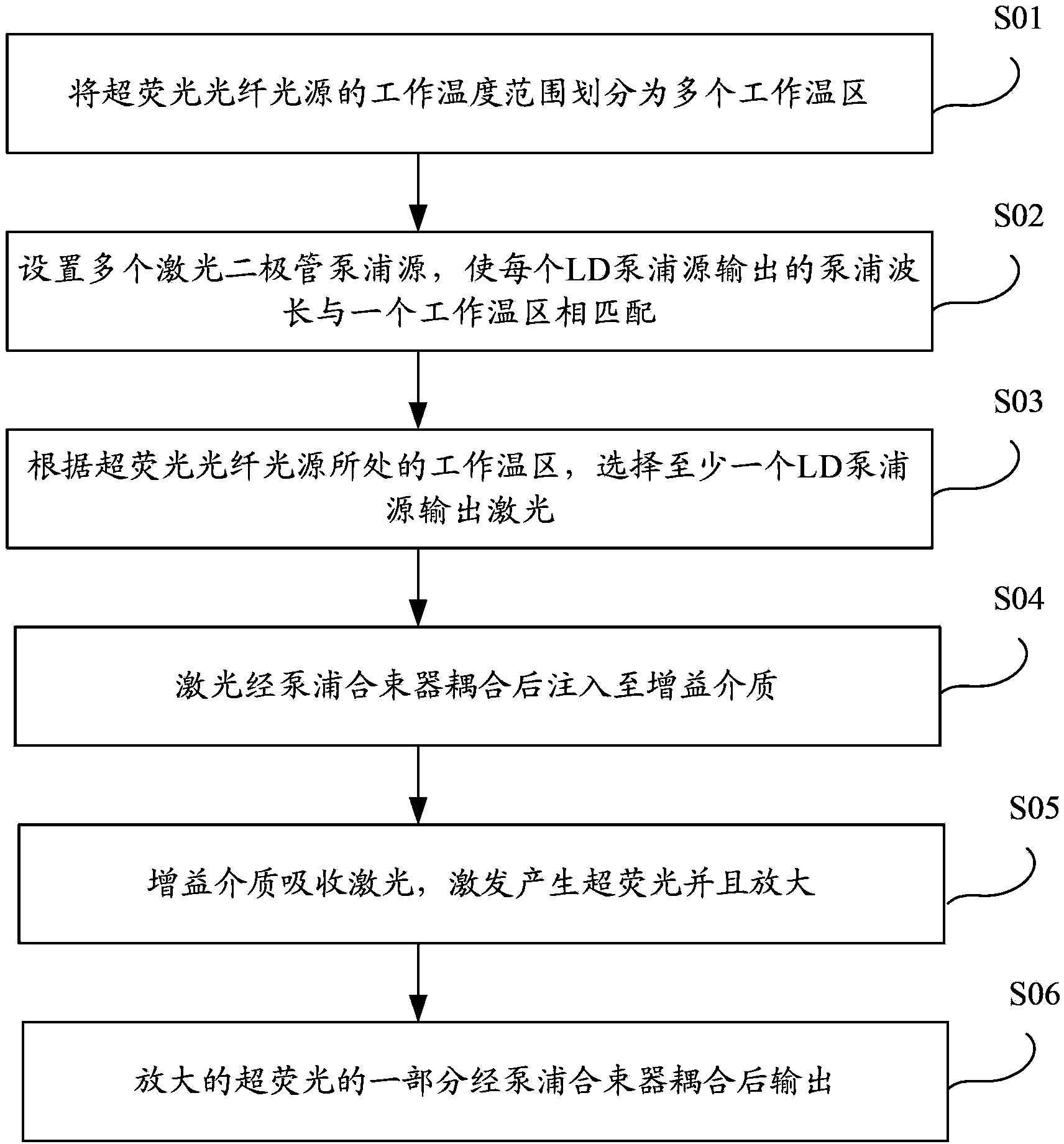
The invention provides a super-fluorescence optical fiber light source and a method for generating super-fluorescence. The super-fluorescence optical fiber light source comprises a plurality of laser diode (LD) pump sources, a plurality of LD driving power supplies, a pump beam combiner and a gain medium, wherein the LD pump sources are used for outputting laser; the working temperature range of the super-fluorescence optical fiber light source is divided into a plurality of working temperature areas; pump wavelength which is output by each LD pump source is matched with one of the working temperature areas; a plurality of LD driving power supplies respectively supply current to a plurality of LD pump sources; the pump beam combiner is connected with an output end of each LD pump source and used for coupling the output laser and injecting the output laser into the gain medium; the gain medium is used for absorbing the laser which is injected by the pump beam combiner to excite generation and amplification of the super-fluorescence; and part of the amplified super-fluorescence is coupled by the pump beam combiner and then output. In a temperature area switching type pump mode, influence of environment temperature change on the pump wavelength and pump power of each LD pump source is reduced, and severe requirements for temperature control of the LD pump sources are greatly reduced.

Description

technical field [0001] The invention relates to the field of fiber optic gyroscopes, in particular to a superfluorescent fiber optic light source and a method for generating superfluorescence. Background technique [0002] In the application process of fiber optic gyroscope, it is easy to be affected by coherence error and noise caused by backscattering in the fiber ring, polarization coupling effect and Kerr effect. In order to suppress the interference of such errors and noises, fiber optic gyroscopes need to use a wide-spectrum light source. For fiber optic gyroscopes used in precision applications, the zero bias stability needs to be 0.001° / h, and the scale factor stability needs to be 10 -6 Next, this requires that the light source not only has a broad output spectrum, but also has good average wavelength stability. As a low-coherence broadband light source, the superfluorescent fiber optic light source has a wide output spectrum and good average wavelength stability,...

Claims


Application Information

Patent Timeline
Patent Type & Authority Patents(China)
IPC IPC(8): H01S3/067H01S3/0941H01S5/042H01S3/10
Inventor 张海涛巩马理陈倚竹闫平柳强黄磊
Owner TSINGHUA UNIV
Learn More