External resonator-type light emitting device

一种外部谐振器、发光装置的技术,应用在光学谐振腔的结构、仪器、光学等方向,能够解决光强度变化等问题

Active Publication Date: 2016-03-30
NGK INSULATORS LTD
View PDF10 Cites 4 Cited by
  • Summary
  • Abstract
  • Description
  • Claims
  • Application Information

AI Technical Summary

Problems solved by technology

However, this FP-type laser oscillates at a wavelength at which the standing wave condition is established, so the longitudinal mode tends to become multimode, and in particular, when the current or temperature changes, the oscillation wavelength changes, thereby changing the light intensity.

Method used


Image

  • External resonator-type light emitting device
  • External resonator-type light emitting device
  • External resonator-type light emitting device

Examples


Embodiment 1

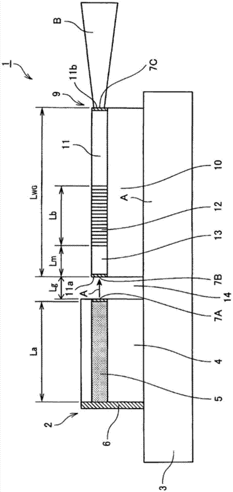
[0157] made as Figure 1-Figure 3 device shown.

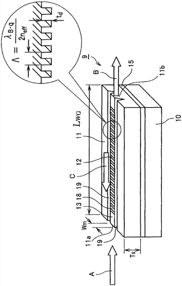
[0158] Specifically, a Ni film is formed on a substrate obtained by z-cutting MgO-doped lithium niobate crystals, and a grating pattern is fabricated in the y-axis direction by photolithography. Afterwards, reactive ion etching was performed using the Ni pattern as a mask to form grating grooves with a pitch interval Λ of 180 nm and a length Lb of 100 μm. The groove depth of the grating is 300nm. In addition, in order to form an optical waveguide propagating in the y-axis, the grating portion was subjected to groove processing with a width Wm of 3 μm and a Tr of 0.5 μm using an excimer laser. Further, on the trench formation surface, a 0.5 μm SiO 2 For the formed buffer layer 17, a black LN substrate was used as a support substrate, and the grating formation surface was bonded.

[0159] Next, the black LN substrate side was attached to a polishing table, and the rear surface of the LN substrate on which the grating was form...

Embodiment 2

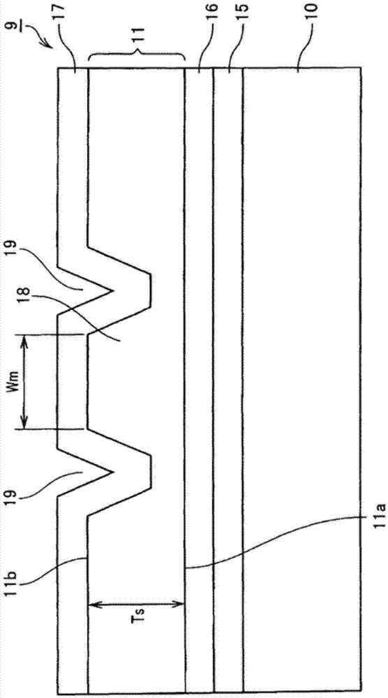
[0184] Produced in the same manner as in Example 1 figure 1 , image 3 device shown. However, the cross-sectional shape of the grating element 21D is Figure 11 (a) The shape shown.

[0185] Specifically, a 0.5 μm lower clad layer of SiO was formed on a support substrate 10 made of quartz by a sputtering device. 2 layer 16, on which 1.2μm Ta 2 o 5 film, forming a high refractive index layer. Next, in Ta 2 o 5 On top, Ti is formed into a film, and a grating pattern is produced by an EB drawing device. Thereafter, fluorine-based reactive ion etching was performed using the Ti pattern as a mask to form a Bragg grating with a pitch interval Λ of 238.5 nm and a length Lb of 100 μm. The groove depth td of the grating is 40 nm.

[0186] Furthermore, in order to form the optical waveguide 20, reactive ion etching was carried out by the same method as above to etch such that the width was Wm3 μm, the optical waveguide 20 remained on both sides, and the high refractive index l...


PUM


Abstract

An external resonator-type light emitting device includes a light source oscillating a semiconductor laser light and a grating device providing an external resonator with the light source. The light source includes an active layer oscillating the semiconductor laser light. The grating device includes an optical waveguide having an incident face to which the semiconductor laser is incident and an emitting face of emitting an emitting light of a desired wavelength, a Bragg grating formed in the optical waveguide, and a propagating portion provided between the incident face and the Bragg grating. Formulas (1) to (4) for the external resonator-type light emitting device are satisfied.

Description

technical field [0001] The present invention relates to an external resonator type light emitting device. Background technique [0002] The semiconductor laser generally adopts the Fabry-Perot (FP) type, and the Fabry-Perot (FP) type semiconductor laser comprises an optical resonator sandwiched by mirrors formed on both end surfaces of the active layer. However, this FP laser oscillates at a wavelength at which the standing wave condition is satisfied, so the longitudinal mode tends to become multimode, and in particular, when the current or temperature changes, the oscillation wavelength changes, thereby changing the light intensity. [0003] Therefore, for purposes such as optical communication and gas sensing, a single-mode laser with high wavelength stability is required. Therefore, distributed feedback (DFB) lasers or distributed Bragg reflective (DBR) lasers were developed. In these lasers, a diffraction grating is provided in a semiconductor, and only a specific wav...

Claims


Application Information

Patent Timeline
Patent Type & Authority Applications(China)
IPC IPC(8): H01S5/14
CPCH01S5/0287H01S5/141H01S5/1039G02B6/124H01S5/02326H01S5/125
Inventor 近藤顺悟山口省一郎吉野隆史武内幸久
Owner NGK INSULATORS LTD
Why Eureka
Try Eureka