
Heat-assisted magnetic recording head and heat-assisted magnetic recording disk drive

An auxiliary magnetic and recording head technology, applied in magnetic recording, recording head configuration/installation, data recording, etc., can solve the problems of high-density recording difficult to achieve, thermally assisted magnetic recording head error rate increase, mode hopping, etc. To achieve the effect of suppressing mode hopping and improving the instability of laser emission

Inactive Publication Date: 2020-05-12
SAE MAGNETICS (HK) LTD
View PDF6 Cites 0 Cited by
  • Summary
  • Abstract
  • Description
  • Claims
  • Application Information

AI Technical Summary

Problems solved by technology

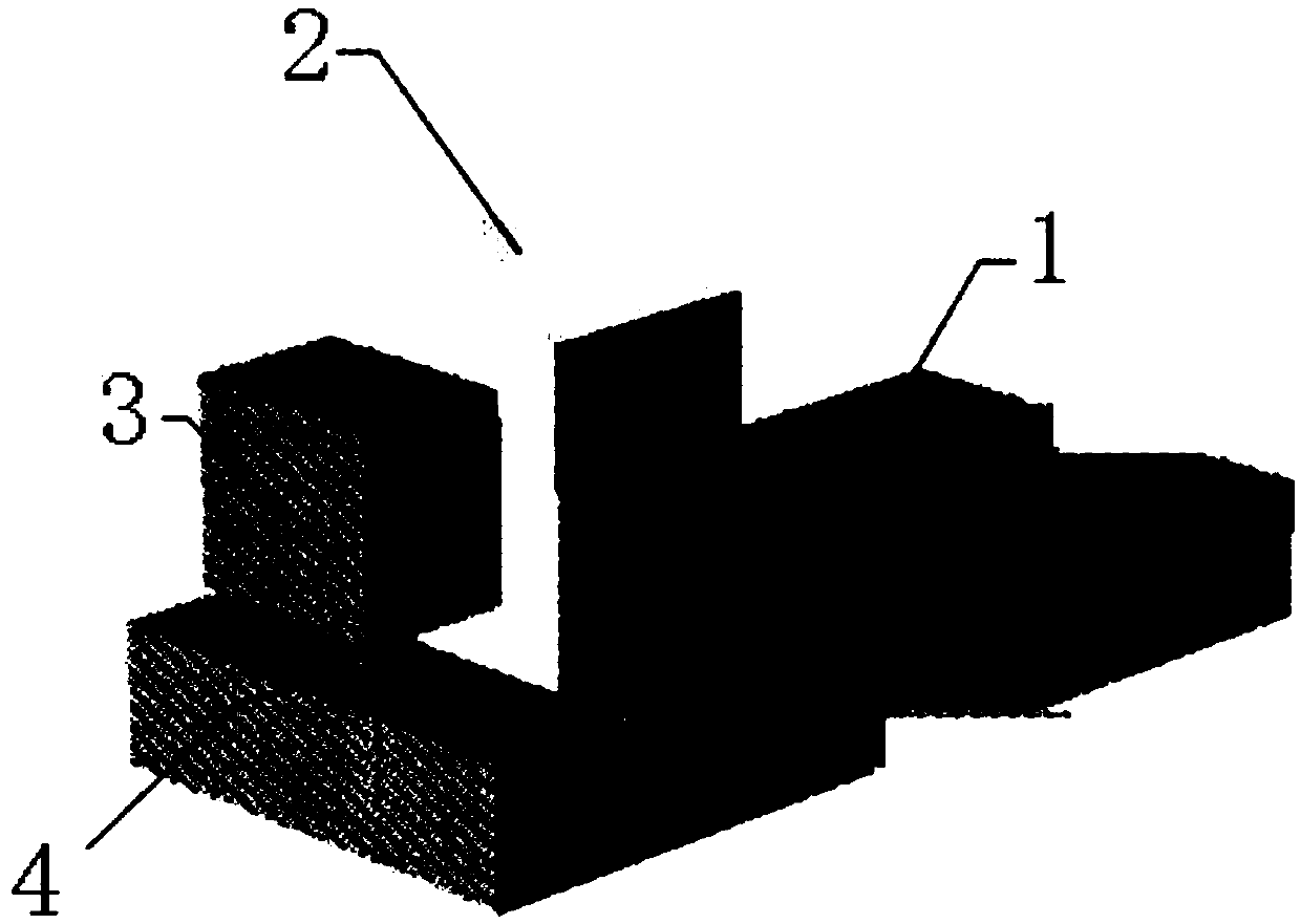
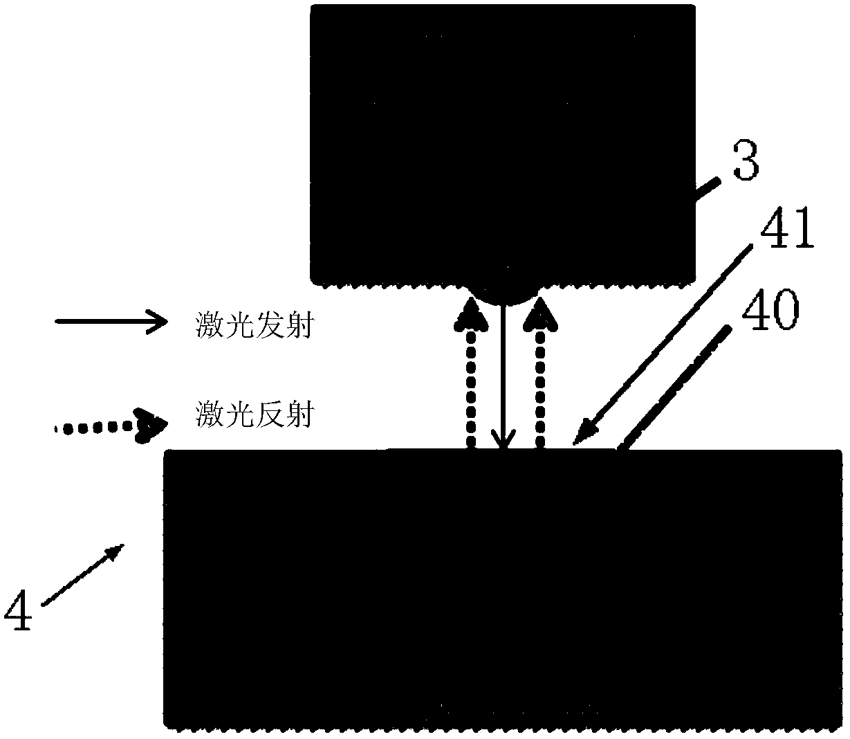
see figure 1 and 2 , the existing heat-assisted magnetic recording head comprises a slider body 1, a laser substrate 2 arranged on the slider body 1 and a laser 3 arranged on the laser substrate 2, a magnetic head 4 is arranged at the front end of the slider body 1, and the magnetic head 4 includes an optical waveguide 40, the light incident surface 41 of the optical waveguide 40 is facing the laser 3, and the light incident surface 41 is a plane, that is, the light incident surface 41 is perpendicular to the incident direction of the laser light emitted by the laser 3, which will cause the laser 3 to emit Part of the laser light is reflected back along the original path, resulting in unstable laser emission and mode hopping of the laser 3. These undesirable effects will lead to a large increase in the error rate of the heat-assisted magnetic recording head, making it difficult to achieve the purpose of high-density recording

Method used


Image

  • Heat-assisted magnetic recording head and heat-assisted magnetic recording disk drive
  • Heat-assisted magnetic recording head and heat-assisted magnetic recording disk drive
  • Heat-assisted magnetic recording head and heat-assisted magnetic recording disk drive

Examples


Embodiment Construction

[0024] In order to have a clearer understanding of the technical features, purposes and effects of the present invention, the specific implementation manners of the present invention will now be described in detail with reference to the accompanying drawings.

[0025] Embodiments of the heat-assisted magnetic recording head and the heat-assisted magnetic recording disk drive of the present invention are described in detail below, examples of these embodiments are shown in the accompanying drawings, wherein the same or similar reference numerals represent the same or similar elements or have the same or similar functional components.

[0026] In describing the heat-assisted magnetic recording head and the heat-assisted magnetic recording disk drive of the present invention, it should be understood that the terms "front", "rear", "upper", "lower", "upper end", "lower end", The orientation or positional relationship indicated by "upper", "lower", etc. is based on the orientation ...


PUM


Abstract

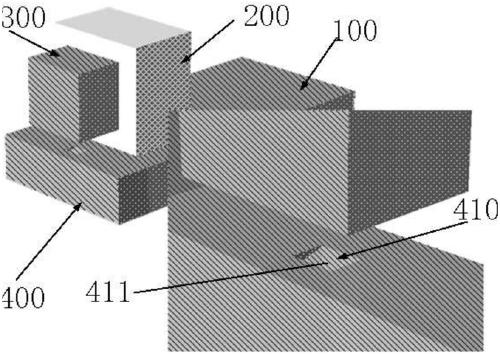
The invention relates to a heat-assisted magnetic recording head and a heat-assisted magnetic recording disk drive. The heat-assisted magnetic recording head comprises a sliding block main body, a laser substrate, a laser and a magnetic head, wherein the laser substrate is arranged on the sliding block main body, the laser device is arranged on the laser substrate, the magnetic head is arranged atthe front end of the sliding block main body, the magnetic head comprises an optical waveguide directly facing the laser device, and the included angle between the incident surface of the optical waveguide and the incident direction of laser incident to the optical waveguide is smaller than 90 degrees; the disk drive comprises a plurality of disks and a head suspension, wherein the heat-assistedmagnetic recording head is arranged at the front end of the head suspension. In the heat-assisted magnetic recording head, the included angle between the incident surface of the optical waveguide andthe incident direction is smaller than 90 degrees, so that the reflected light of the incident surface cannot return to the laser along the incident direction, the laser emission instability can be improved, and the mode hopping can be inhibited.

Description

technical field [0001] The present invention relates to disk drive technology, more specifically, to a heat-assisted magnetic recording head and a heat-assisted magnetic recording disk drive. Background technique [0002] In order to increase the magnetic recording density, the previous method is to reduce the grain size as much as possible, but with the continuous increase of the storage density, it is found that the reduction of the grain volume is limited by the superparamagnetic effect. The relaxation time of the magnetic order decreases exponentially when the size of the recording spot decreases; when the measurement temperature of the recording spot increases, the relaxation time of the magnetic order also decreases exponentially. Therefore, both the reduction of the volume of the recording point and the increase of the temperature will lead to the magnetic instability of the recording point. [0003] In order to break through the limit of magnetic recording density c...

Claims


Application Information

Patent Timeline
Patent Type & Authority Applications(China)
IPC IPC(8): G11B5/48
CPCG11B5/4866G11B5/314G11B2005/0021G11B5/3133G11B5/6088G11B5/60
Inventor 藤井隆司黄坚辉西岛夏夫黄林陈世雄齐斌郭文荣
Owner SAE MAGNETICS (HK) LTD
Learn More