

External resonator type light emitting device
A technology of external resonators and light-emitting devices, applied in the structure of optical resonators, instruments, optics, etc., can solve problems such as changes in light intensity, achieve the effects of suppressing mode hopping, improving wavelength stability, and suppressing changes in light intensity
- Summary
- Abstract
- Description
- Claims
- Application Information
AI Technical Summary
Problems solved by technology
Method used
Image

Examples
Embodiment 1
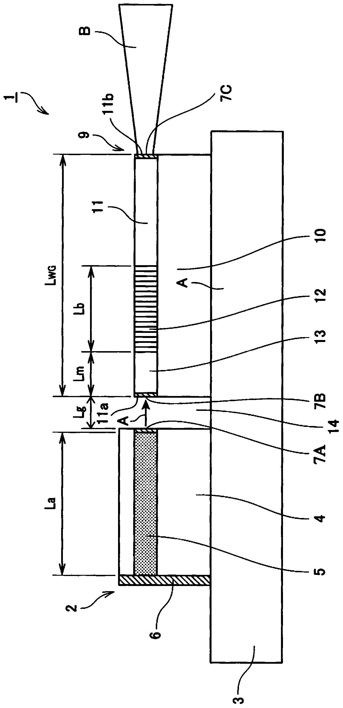
[0174] made as Figure 1 ~ Figure 3 device shown.
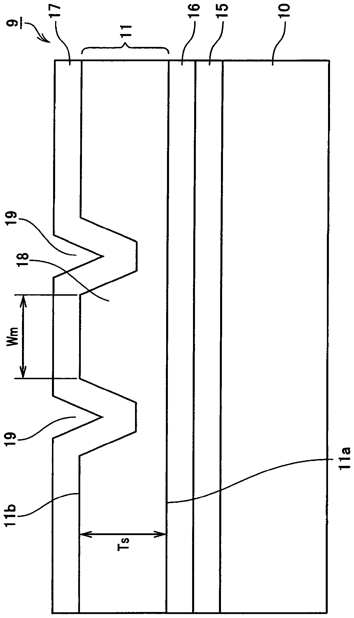
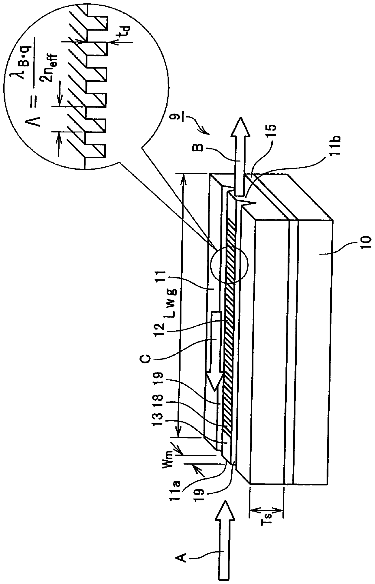
[0175] Specifically, a Ti film is formed on a substrate obtained by z-cutting MgO-doped lithium niobate crystals, and a grating pattern is fabricated in the y-axis direction by photolithography. Afterwards, using the Ti pattern as a mask, fluorine-based reactive ion etching was used to form b100μm grating groove. The groove depth of the grating is 300nm. In addition, in order to form an optical waveguide propagating in the y-axis, the grating portion was subjected to groove processing with a width Wm of 3 μm and a Tr of 0.5 μm using an excimer laser. Further, a sputtering device was used to form SiO 2 The buffer layer 17 is constituted by using a black LN substrate as a support substrate and bonding the grating formation surface.
[0176] Next, the black LN substrate side was attached to a polishing table, and the rear surface of the LN substrate on which the grating was formed was precisely polished to a thickness (Ts) ...
Embodiment 2
[0201] made figure 1 with Figure 4 device shown.
[0202] Specifically, a Ti film is formed on a substrate obtained by z-cutting MgO-doped lithium niobate crystals, and a grating pattern is fabricated in the y-axis direction by photolithography. Afterwards, using the Ti pattern as a mask, fluorine-based reactive ion etching was used to form a pattern with a pitch interval Λ of 214nm and a length L b 100μm grating groove. The groove depth of the grating is 40nm. In addition, in order to form an optical waveguide propagating in the y-axis, the grating portion was subjected to groove processing with a width Wm of 3 μm and a Tr of 0.5 μm using an excimer laser. Further, a sputtering device was used to form SiO 2 The buffer layer 17 is formed by using a black LN substrate as a support substrate, and the grating formation surface is bonded. The so-called black LN refers to lithium niobate in an oxygen-deficient state, which can suppress the generation of charge due to pyroele...
Embodiment 3
[0217] In the same way as in Example 2, a pitch interval Λ of 222 nm and a length L b 100μm grating groove. The groove depth of the grating is 40nm. Regarding the optical characteristics of the grating element, using a super light-emitting diode (SLD) as a broadband wavelength light source, the light is input to the grating element, and the output light is analyzed by a spectrum analyzer, thereby evaluating reflection characteristics from its transmission characteristics. As a result, for the TE mode, a central wavelength of 975nm, a maximum reflectance of 20%, and a full width at half maximum Δλ G 2nm characteristics.
[0218] Next, if figure 1 Install the laser module as shown. The light source element is an ordinary GaAs laser, and there is no AR coating on the exit end face.
[0219] Light source component specifications:
[0220] Center wavelength: 977nm
[0221] Output: 50mW
[0222] Half value width: 0.1nm
[0223] Laser element length: 250μm
[0224] Installati...
PUM
| Property | Measurement | Unit |
|---|---|---|
| wavelength | aaaaa | aaaaa |
| length | aaaaa | aaaaa |
| thickness | aaaaa | aaaaa |
Abstract
Description
Claims
Application Information