External resonator type light emitting device

A technology of external resonators and light-emitting devices, applied in the structure of optical resonant cavities, instruments, optics, etc., can solve problems such as light intensity changes

Active Publication Date: 2016-03-23
NGK INSULATORS LTD
View PDF14 Cites 0 Cited by
  • Summary
  • Abstract
  • Description
  • Claims
  • Application Information

AI Technical Summary

Problems solved by technology

However, this FP-type laser oscillates at a wavelength at which the standing wave condition is established, so the longitudinal mode tends to become multimode, and in particular, when the current or temperature changes, the oscillation wavelength changes, thereby changing the light intensity.

Method used


Image

  • External resonator type light emitting device
  • External resonator type light emitting device
  • External resonator type light emitting device

Examples


Embodiment

[0137] (Example)

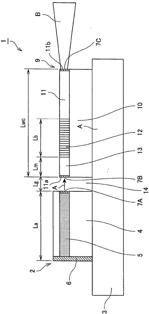
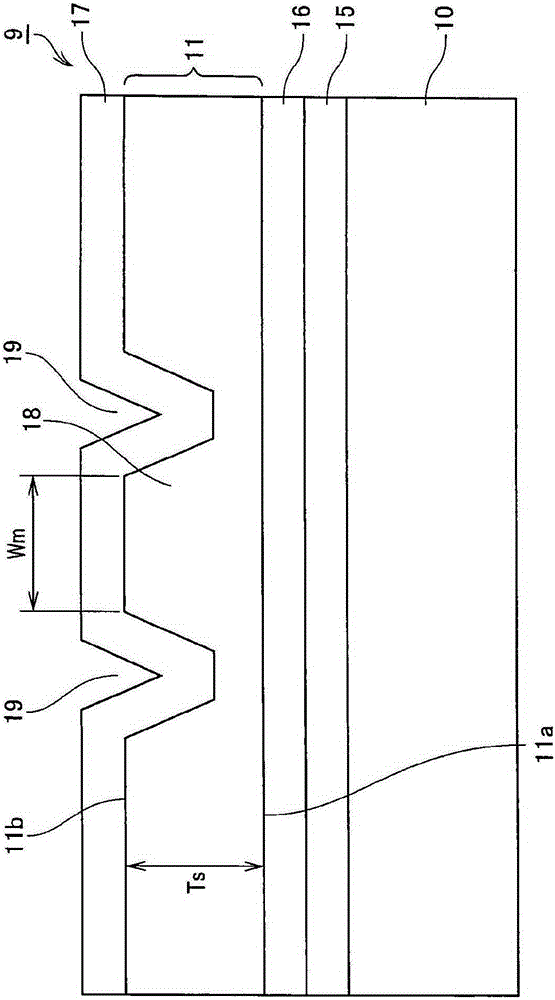
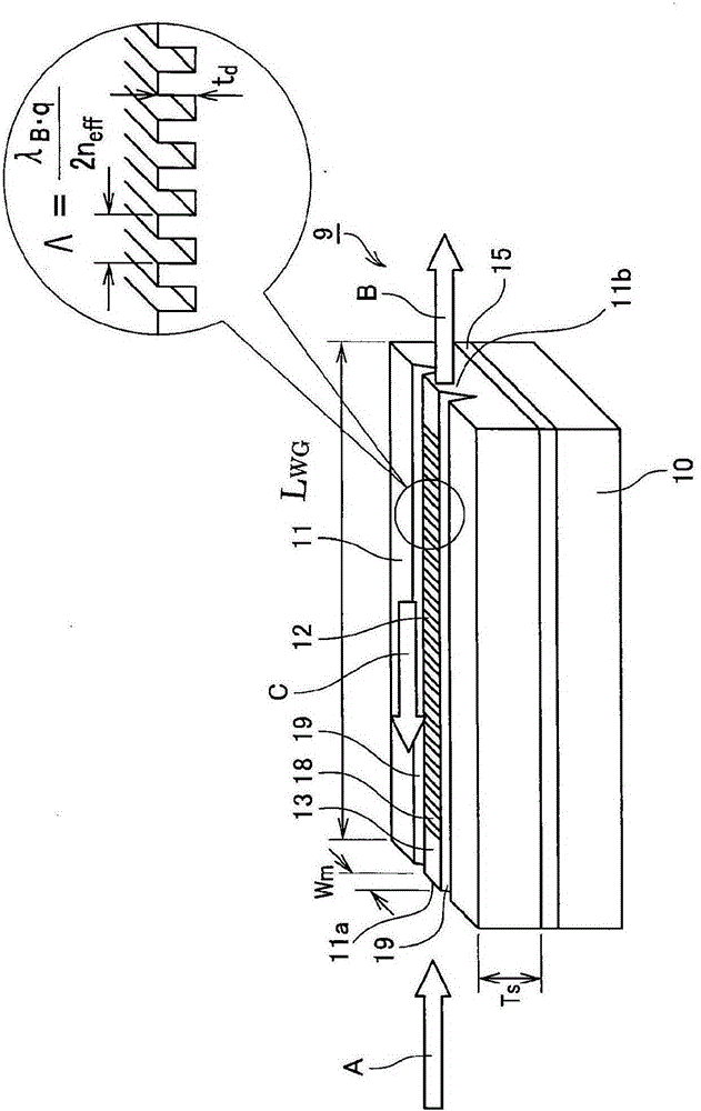
[0138] made as Figure 1-Figure 3 device shown.

[0139] Specifically, a film of Ni is formed on a substrate in which MgO-doped lithium niobate crystals are cut into z-plates, and a grating pattern is fabricated in the y-axis direction by photolithography. Thereafter, reactive ion etching is performed through the mask Ni pattern, thereby forming a pitch (pitch) interval Λ of 180 nm and a length L b 100μm grating groove. The groove depth of the grating is 300nm. In addition, in order to form an optical waveguide propagating in the y-axis, the grating portion was subjected to groove processing with a width Wm of 3 μm and a Tr of 0.5 μm using an excimer laser. Further, on the trench formation surface, the SiO 2 The buffer layer 17 formed was formed at a thickness of 0.5 μm, and a black LN substrate was used as a support substrate, and the grating formation surface was bonded. Here, the black LN substrate refers to, from LN (LiNbO 3 ) crystallization remo...


PUM


Abstract

The external resonator type light-emitting device includes a light source for oscillating a semiconductor laser, and a grating element constituting the light source and the external resonator. The light source includes an active layer for oscillating the semiconductor laser. The grating element is provided with: an optical waveguide having an incident surface into which the semiconductor laser is incident and an exit surface emitting outgoing light of a desired wavelength; a Bragg grating formed in the optical waveguide; and a propagation portion provided on the incident surface and between Bragg gratings. This external resonator type light-emitting device satisfies the relationship of the formula (1) to the formula (4).

Description

technical field [0001] The present invention relates to an external resonator type light emitting device. Background technique [0002] A semiconductor laser generally adopts a Fabry-Perot (FP) type, and the Fabry-Perot (FP) comprises an optical resonator sandwiched between mirrors formed on both end surfaces of an active layer. However, this FP laser oscillates at a wavelength at which the standing wave condition is satisfied, so the longitudinal mode tends to become multimode, and in particular, when the current or temperature changes, the oscillation wavelength changes, thereby changing the light intensity. [0003] Therefore, for purposes such as optical communication and gas sensing, a single-mode laser with high wavelength stability is required. Therefore, distributed feedback (DFB) lasers or distributed Bragg reflective (DBR) lasers were developed. In these lasers, a diffraction grating is provided in a semiconductor, and only a specific wavelength is oscillated by ...

Claims


Application Information

Patent Timeline
Patent Type & Authority Patents(China)
IPC IPC(8): H01S5/14H01S5/12
CPCH01S5/0287H01S5/141H01S5/1039G02B6/124H01S5/02326H01S5/125
Inventor 近藤顺悟山口省一郎吉野隆史武内幸久
Owner NGK INSULATORS LTD
Why Eureka
Try Eureka