Magnetic valve and driver assistance device having such a magnetic valve

A technology for driver assistance and solenoid valves, which is applied in the direction of valve operation/release devices, valve devices, valve lifts, etc., can solve the problems of reduced durability of solenoid valves, and achieve the effect of improving durability

Inactive Publication Date: 2012-09-19
ROBERT BOSCH GMBH
View PDF3 Cites 0 Cited by
  • Summary
  • Abstract
  • Description
  • Claims
  • Application Information

AI Technical Summary

Problems solved by technology

The support of the closure element known from the prior art on the base body by means of the support surface can in some cases lead to a reduction in the durability of the solenoid valve, so that this solenoid valve may have to be replaced frequently

Method used


Image

  • Magnetic valve and driver assistance device having such a magnetic valve
  • Magnetic valve and driver assistance device having such a magnetic valve
  • Magnetic valve and driver assistance device having such a magnetic valve

Examples


Embodiment Construction

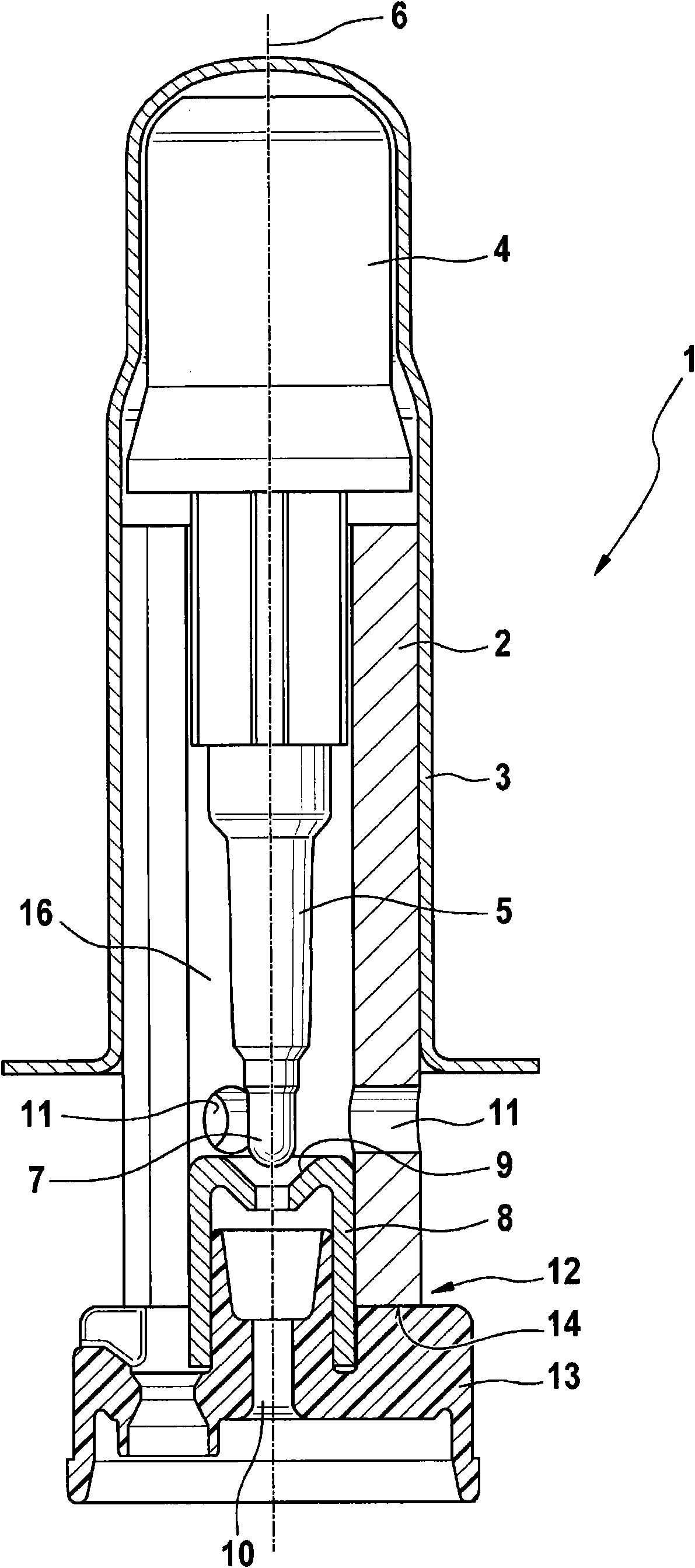
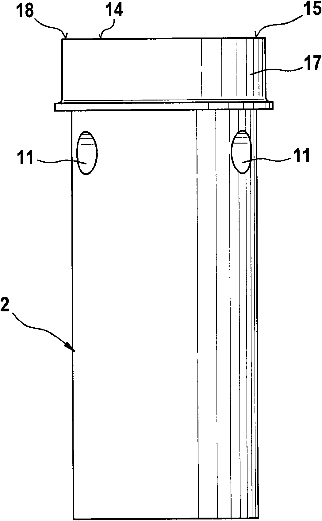
[0018] figure 1 A cutaway side view of a solenoid valve 1 is shown, which are known from the prior art in the embodiment shown here. The solenoid valve comprises a base body 2 which is also referred to as a valve insert. The base body 2 is at least partially surrounded by a housing 3 . In the base body 2 , a magnetic armature 4 and an actuating element 5 connected thereto are mounted axially movable relative to a longitudinal axis 6 of the solenoid valve 1 . The actuating element 5 has a sealing element 7 on its side facing away from the magnetic armature 4, which cooperates with a valve seat 9 formed in the sealing body 8 to establish or disconnect the first fluid connection 10 to the second fluid connection. Fluid connection of a fluid connection 11 , the first fluid connection being designed as an inlet connection and the second fluid connection being an outlet connection.

[0019] The closing element 13 is connected to the main body in an end region 12 of the main body ...


PUM


Abstract

The invention relates to a magnetic valve (1) having a main body (2) and a closure element (13) which is connected to an end region (12) of the main body (2) and which can be impinged by a fluid pressure, wherein the main body (2) has at least one first support surface (14) allocated to the closure element (13) in the end region (12) thereof. A support element (17) is provided which is connected to the main body (2) and has at least one other, second support surface (18) serving as a bearing surface (15) or forms the bearing surface (15) together with the first support surface (14), wherein the bearing surface (15) is larger than the first support surface (14). The invention further relates to a driver assistance device having such a magnetic valve (1).

Description

technical field [0001] The invention relates to a solenoid valve with a base body and a closure element connected to an end region of the base body to which fluid pressure can be applied, wherein the base body has at least one valve in its end region which is assigned to the closure element. The first support surface of the component. The invention also relates to a driver assistance device. Background technique [0002] Solenoid valves of the type mentioned at the outset are known from the prior art. They are designed, for example, as non-flow-opening or non-flow-closing 2 / 2-way solenoid valves. Such solenoid valves are used as technical components to control the intake or discharge of gases or liquids, or to control or regulate the direction of flow. The inlet port, through which the fluid (ie gas or liquid) passes into the solenoid valve, is usually arranged in a closure element which is connected to the base body or the end region of the base body. The force caused b...

Claims


Application Information

Patent Timeline
Patent Type & Authority Applications(China)
IPC IPC(8): B60T8/36F16K31/06
CPCB60T8/363F16K1/42F16K31/0658
Inventor H·古根莫斯M·迪纳曼F·米勒A·弗里茨E·菲尔
Owner ROBERT BOSCH GMBH
Why Eureka
Try Eureka