
Foam-dispensing pump container

一种泡沫、泵式的技术,应用在喷射装置、液体喷射装置、关闭等方向,达到减少逆流、改善使用性的效果

Active Publication Date: 2012-09-26
DAIWA CAN
View PDF6 Cites 15 Cited by
  • Summary
  • Abstract
  • Description
  • Claims
  • Application Information

AI Technical Summary

Problems solved by technology

[0007] The present invention is made in view of the above-mentioned problems of the prior art, that is, the problem to be solved by the present invention is to provide a pump that improves usability when the foam or liquid flows back into the pump after the foam is sprayed. Pump Foam Dispenser Container

Method used


Image

  • Foam-dispensing pump container
  • Foam-dispensing pump container
  • Foam-dispensing pump container

Examples


Embodiment Construction

[0036] Next, preferred embodiments of the present invention will be described with reference to the drawings.

[0037] Structure of the pump foam ejection container

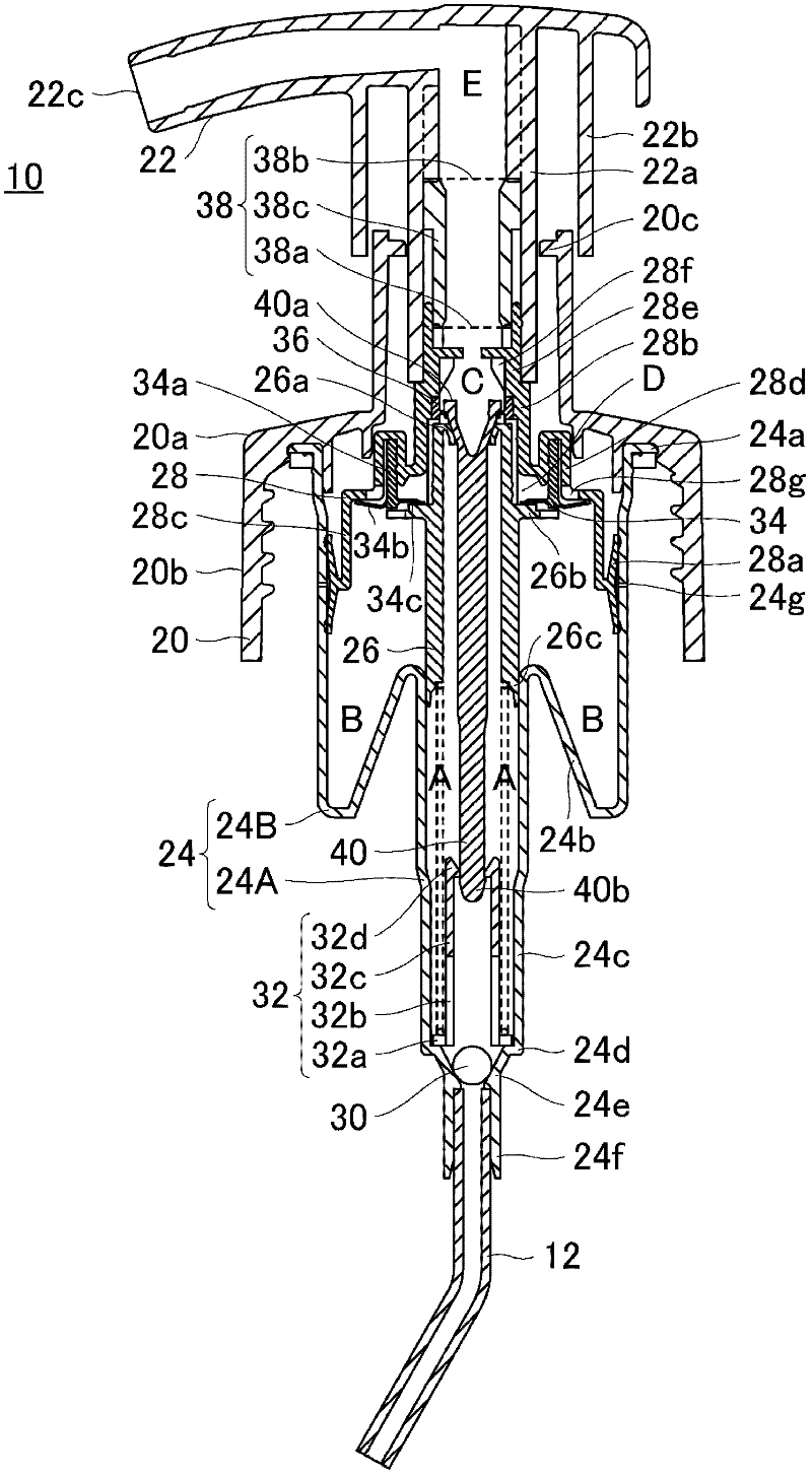
[0038] The pump-type foam spray container of this embodiment includes: a container body, which is used to accommodate liquid; a spray pump body, which is detachably installed on the mouth of the upper end of the container body; a pipe body, which is connected with the spray pump The body is connected and extends to the interior of the container body.

[0039] figure 1 It is a sectional view showing the discharge pump body 10 of the pump-type foam discharge container according to one embodiment of the present invention (a front sectional view in a state where the nozzle head is located at the terminal end of the rise).

[0040] A base cap (base cap) portion 20 is provided below the discharge pump body 10 of the present embodiment and has a skirt shape, and internal threads are formed on the inner peripheral su...


PUM


Abstract

The invention provides a foam-dispensing pump container which is improved when the foam or liquid backflows to the inside of a pump after being dispensed to reduce the usability. The foam-dispensing pump container according to the present invention has the valve seat portion which protrudes inwardly below the air-liquid mixing unit and which is formed of the flexible member that can come into contact with the outer peripheral face of the latch portion of the rod-shaped valve body, and immediately after the nozzle head starts rising, the flexible valve seat portion comes into contact with the rod-shaped valve body before the upper opening end of the liquid chamber comes into contact with the rod-shaped valve body, thereby significantly reducing a backflow of the foam or liquid into the air passage, and consequently improving the usability of the foam-dispensing pump container.

Description

technical field [0001] The present invention relates to a pump-type foam spray container that sprays foam from a foam spray port, and particularly relates to the improvement of the situation where the foam or liquid flows back into the pump after the foam is sprayed, resulting in a drop in usability. The foam is formed by mixing the air and the foaming liquid in the body of the container by depressing the nozzle head out of the container. Background technique [0002] Conventionally, containers of various structures have been proposed as pump-type foam ejection containers. In this pump-type foam ejection container, the nozzle head of the nozzle body provided on the upper part of the container body is pressed down to release the foam contained in the container body. The liquid is mixed with the air sucked from the outside of the container to form foam, and the foam is sprayed out of the container through the foam passage inside the nozzle head. In addition, in such a convent...

Claims


Application Information

Patent Timeline
Patent Type & Authority Applications(China)
IPC IPC(8): B65D47/34
CPCB05B11/0064B05B11/3047B05B11/3087B05B7/0037B05B11/1047B05B11/1087B65D47/00B05B11/00B65D83/00
Inventor 植平庄治斋藤大亮
Owner DAIWA CAN
Learn More