
LED (light emitting diode) lamp socket

A technology of LED lamp beads and lamp sockets, which is applied in the cooling/heating device, lighting device, light source and other directions of lighting devices, can solve the problems of shortening the service life of LED lamps, damage of LED lamp beads, and temperature rise of LED lamps, and achieves heat dissipation. Simple way, good service life, easy to replace

Inactive Publication Date: 2014-04-23
陈广友
View PDF7 Cites 0 Cited by
  • Summary
  • Abstract
  • Description
  • Claims
  • Application Information

AI Technical Summary

Problems solved by technology

[0002] At present, the existing LED lighting lamps in the domestic and foreign markets have an integral structure of lamp beads, power supply and lamp holder. Because the lamp beads of the existing LED lamps are welded to the aluminum substrate with the positive and negative ends of the lamp beads On the front side, the power wires are welded on the front side of the aluminum substrate. The high temperature of the lamp bead during welding is also a damage to the LED lamp bead. Contact, the LED lamp bead uses the aluminum substrate as the electrical substrate and dissipates heat through the coated thermal paste, and the dissipated heat is then dissipated to the surrounding space of the LED lamp through the heat sink of the lamp holder. Only one conduction path can dissipate the heat, the heat dissipation efficiency is low, and the heat dissipation effect is not good, especially the long-term use is easy to cause the temperature rise of the LED lamp, thus shortening the service life of the LED lamp

Method used


Image

  • LED (light emitting diode) lamp socket
  • LED (light emitting diode) lamp socket
  • LED (light emitting diode) lamp socket

Examples


Embodiment Construction

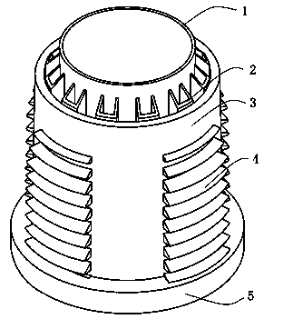
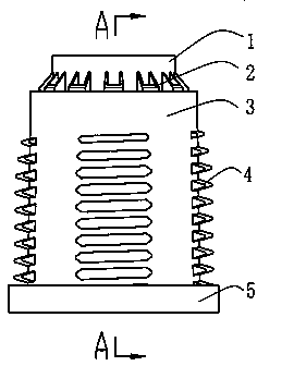
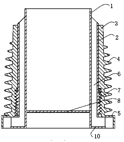
[0016] Such as Figure 1-5 As shown, the LED lamp holder of the present invention includes a lamp holder body 1 with a lamp holder inner plate 8, the lamp holder inner plate 8 is used to install LED lamp beads, and several spaced apart lamp holders are arranged on the outer periphery of the lamp holder body 1. Vertical air pipe 2, and the outer peripheral surface of the vertical air pipe 2 is provided with external threads 9, the lamp holder body 1 is provided with a lamp holder shell 3, and the inner surface of the lamp holder shell 3 is provided with a thread that matches the external thread. The inner thread 7 connects the lamp holder shell with the lamp holder body through the matching inner and outer threads, and the vertical ventilation pipe 2 isolates the lamp holder body 1 from the lamp holder shell 3 to form a ventilation channel 6; along the lamp holder body 1 The lower end surface is provided with an outwardly extending annular lamp holder outer plate 11; the lamp h...


PUM


Abstract

The invention discloses an LED (light emitting diode) lamp socket comprising a lamp socket body with a lamp socket inner plate, wherein the lamp socket inner plate is used for installing an LED bulb; the periphery of the lamp socket body is provided with a plurality of vertical ventilating pipes which are arranged at intervals; the peripheral surface of each ventilating pipe is provided with an outer thread; a lamp socket housing is arranged outside the lamp socket body; and the inner surface of the lamp socket housing is provided with an inner thread matched with the outer thread. According to the LED lamp socket, ventilating channels are arranged between the lamp socket body and the lamp socket housing, hot air flows are directly and upwards dispersed to the top of a ceiling through the ventilating channels, therefore the heat radiation way of the LED lamp socket is simpler than that of a common heat radiation fin type lamp socket, a heat radiation effect is better and the service life of the LED lamp can be ensured well; and meanwhile, the detachable LED lamp socket structure facilitates the replacement of a damaged LED lamp and damaged power supply fittings, and the LED lamp socket is convenient to use.

Description

technical field [0001] The invention relates to an LED lamp holder. Background technique [0002] At present, the existing LED lighting lamps in the domestic and foreign markets have an integral structure of lamp beads, power supply and lamp holder. Because the lamp beads of the existing LED lamps are welded to the aluminum substrate with the positive and negative ends of the lamp beads On the front side, the power wires are welded on the front side of the aluminum substrate. The high temperature of the lamp bead during welding is also a damage to the LED lamp bead. Contact, the LED lamp bead uses the aluminum substrate as the electrical substrate and dissipates heat through the coated thermal paste, and the dissipated heat is then dissipated to the surrounding space of the LED lamp through the heat sink of the lamp holder. Only one conduction path can dissipate the heat, the heat dissipation efficiency is low, and the heat dissipation effect is not good, especially the lon...

Claims


Application Information

Patent Timeline
Patent Type & Authority Patents(China)
IPC IPC(8): F21V29/00F21Y101/02F21V29/83F21Y115/10
Inventor 陈广友
Owner 陈广友
Learn More