Electronic ballast of electrodeless lamp

An electronic ballast and electrodeless lamp technology, applied in electric light sources, electrical components, lighting devices, etc., can solve the problems of poor circuit reliability and many solder joints, and achieve the effect of small deviation range, stable frequency, and avoidance of burnout

Inactive Publication Date: 2012-09-26
江苏立德照明产业有限公司
View PDF9 Cites 0 Cited by
  • Summary
  • Abstract
  • Description
  • Claims
  • Application Information

AI Technical Summary

Problems solved by technology

Due to the many components contained in the protection circuit 112, there are also many solder joints of the corresponding components, resulting in poor reliability of the circuit

Method used


Image

  • Electronic ballast of electrodeless lamp
  • Electronic ballast of electrodeless lamp
  • Electronic ballast of electrodeless lamp

Examples


Embodiment Construction

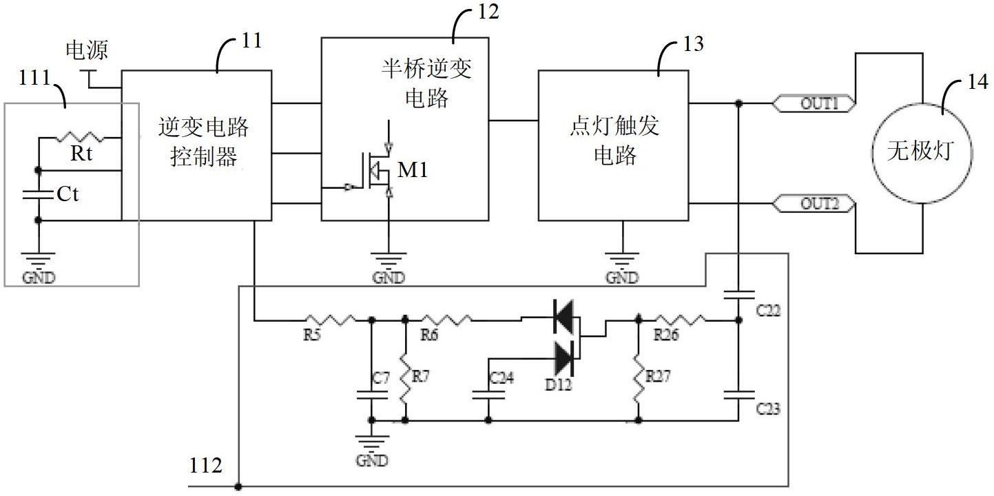
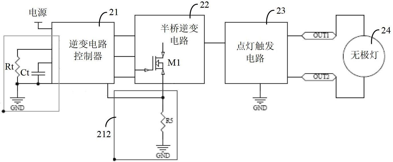
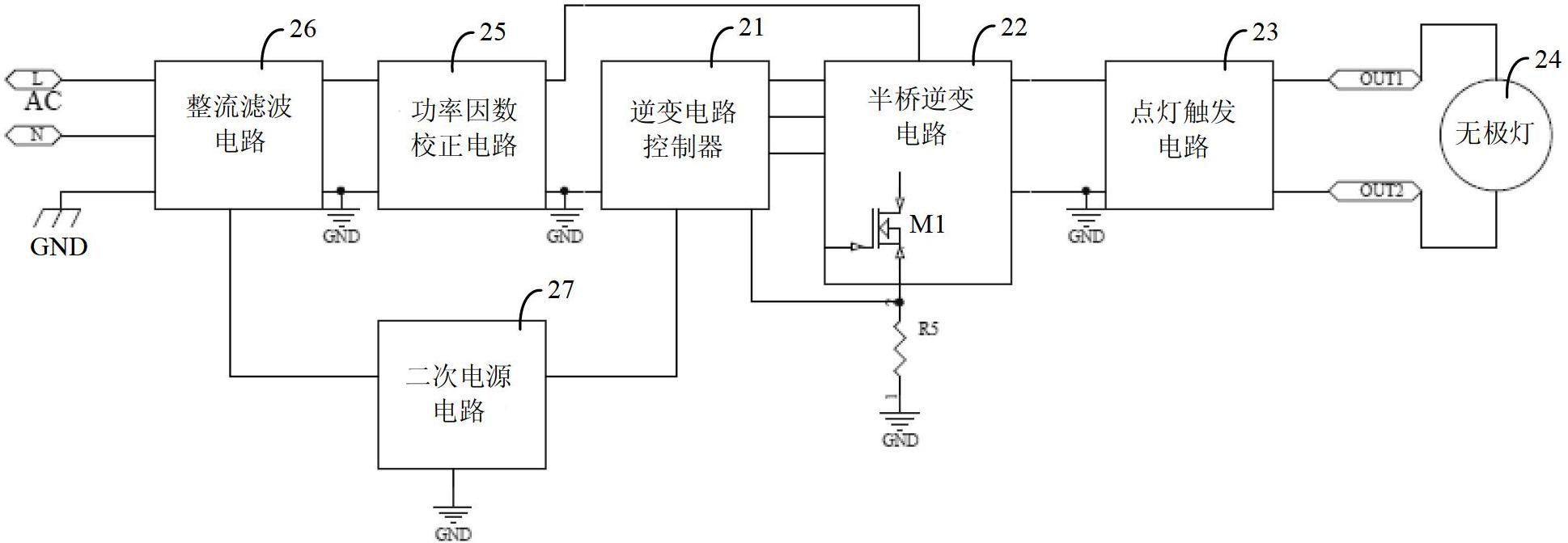
[0021] Electronic ballasts for electrodeless lamps in the prior art usually use inverter circuit controllers used in electronic ballasts for ordinary energy-saving lamps, such as IR2156S chips, which are easy to burn out. After research, the inventor found that the reason is mainly due to the low frequency of the output signal of the inverter circuit controller used in the electronic ballast of ordinary energy-saving lamps, which is usually lower than the working frequency of the electrodeless lamp. For example, the working frequency of common energy-saving lamps in the market is only 20KHz ~ 60KHz. Using the inverter circuit controller in the electronic ballast of energy-saving lamps to construct the electronic ballast for electrodeless lamps will cause the output signal frequency of the inverter circuit controller to be reduced. Forcibly increasing to hundreds of KHz, which is much higher than the design specification frequency, increases the risk of burning the inverter circ...


PUM


Abstract

The invention provides an electronic ballast of an electrodeless lamp. The electronic ballast of the electrodeless lamp comprises an inverter circuit controller, a half-bridge inverter circuit and a light trigger circuit, wherein the frequency of the output power of the inverter circuit controller is larger than or equal to the work frequency of the electrodeless lamp; the input end of the half-bridge inverter circuit is connected with the output end of the inverter circuit controller; and the input end of the light trigger circuit is connected with the half-bridge inverter circuit, and the output end of the light trigger circuit is connected with the electrodeless lamp. According to the electronic ballast of the electrodeless lamp, disclosed by the invention, the inverter circuit controller and an inverter circuit can be prevented from being burnt, and the electronic ballast is favorable for supplying the stable power and higher reliability.

Description

technical field [0001] The invention relates to an electronic ballast for an electrodeless lamp, in particular to an electronic ballast for a low frequency electrodeless lamp. Background technique [0002] figure 1 A low-frequency electrodeless lamp electronic ballast in the prior art is shown, mainly including: an inverter circuit controller 11; a half-bridge inverter circuit 12 connected with the inverter circuit controller 11; 12 connected to the lighting trigger circuit 13, and the lighting trigger circuit 13 is configured to be connected to the electrodeless lamp 14. Wherein, the inverter circuit controller 11 in conventional low-frequency electrodeless lamp electronic ballasts usually adopts the inverter circuit controller used in ordinary energy-saving lamp electronic ballasts, but the inverter circuit controller is relatively easy to be burned. [0003] also, figure 1 In the shown electronic ballast for low-frequency electrodeless lamps, the resistance input termi...

Claims


Application Information

Patent Timeline
Patent Type & Authority Applications(China)
IPC IPC(8): H05B41/282
Inventor 李维德徐珺陈艳
Owner 江苏立德照明产业有限公司
Why Eureka
Try Eureka