
Metering method of particle counter

A particle counter and measurement method technology, applied in the field of measurement, can solve the problems of difficult measurement result consistency, inability to meet application requirements, difficult to improve reliability, etc. Effect

Pending Publication Date: 2021-10-26
SUZHOU SUXIN ENVIRONMENT SCI & TECH CO LTD
View PDF0 Cites 0 Cited by
  • Summary
  • Abstract
  • Description
  • Claims
  • Application Information

AI Technical Summary

Problems solved by technology

It can be understood that the existing particle counter measurement method has low working efficiency, and it is difficult to achieve the consistency of measurement results among multiple (each) particle counters, and it is difficult to improve the reliability and cannot meet the application requirements.

Method used


Image

  • Metering method of particle counter
  • Metering method of particle counter
  • Metering method of particle counter

Examples


Embodiment 1

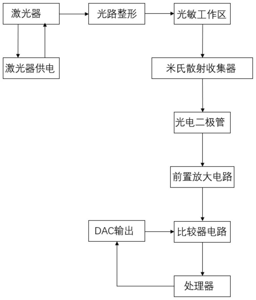
[0037] In Embodiment 1 of the present invention, as figure 1 As shown, the particle counter in this embodiment is composed of an optical module providing a working light beam, a working area for detection, a photoelectric receiving module for receiving and converting optical signals, a processor, a comparator and a DAC. The working area is the photosensitive working area and the Mie scattering collector. The optical module includes a laser as a laser light source and its power supply components. By adjusting the power supply of the laser, the output light intensity of the laser can be adjusted. In this embodiment, the airflow of a certain concentration of particles passes through the light field of the photosensitive working area, and the light emitted by a single particle after passing through the Mie scattering collector is collected by the photoelectric receiving module and projected onto the photosensitive element of the photoelectric receiving module . The photosensitiv...

Embodiment 2

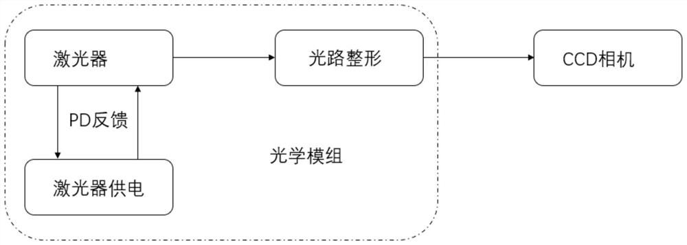
[0043] Because the light intensity of the particle counter is required to be uniform, and the light intensity at each point in the entire working area is the same, it is required that the light intensity of the optical module of each particle counter has better consistency. Such as Figure 5 As shown, the difference between Embodiment 2 and Embodiment 1 is that an optical power meter is used in addition to a CCD camera when calibrating the spot. In step S1, the light intensity of the working beam required by the actual application is also used. The light intensity is equal to the unit The optical power of the area, thereby preset the standard total value of the optical power of the working area, measure the optical power of the working beam, and adjust the optical power of the working area to be consistent with the standard total value based on the measurement results, thereby calibrating the optical power of the working beam powerful. In this embodiment, multiple particle co...


PUM


Abstract

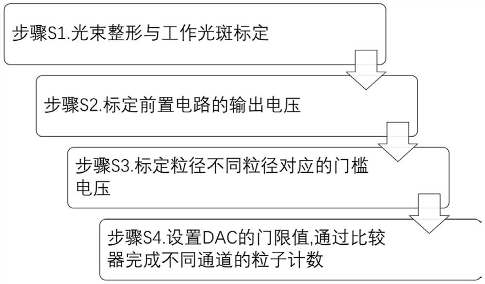
The invention provides a metering method of a particle counter. The metering method comprises the following steps of shaping an output light beam of a laser to obtain a working light beam, calibrating the output voltage of the pre-amplification circuit, calibrating threshold voltages corresponding to different particle sizes, and setting a threshold value of a DAC, and completing counting of different channels through a comparator. The DAC is combined with the comparator, so that counting can be efficiently and accurately completed, the cost is low, and the power consumption is small; metering is conducted after theparticle counter is calibrated, the steps are simple, the deviation range of the final metering result is greatly reduced, metering efficiency is high, reliability is good, implementation is easy, and further popularization and development of the metering technology are facilitated.

Description

technical field [0001] The invention belongs to the technical field of metering, in particular to a working method for metering using an optical particle counter. Background technique [0002] Metrology is the science of detection, and it is a measurement that uses technical and legal means to achieve unit unity and accurate and reliable values. The "Measurement Law of the People's Republic of China" also has relevant regulations on measurement work. If the measurement practices do not meet the requirements, there may be legal risks. [0003] Light scattering laser particle counters are generally used to measure the number and particle size distribution of dust particles per unit volume in a clean environment. Its measurement method is based on the principle of Mie scattering. After the detection laser of the optical module is scattered by dust particles, it is received by the photoelectric receiving module and generates a pulse signal. The pulse signal is output and amplif...

Claims


Application Information

Patent Timeline
Patent Type & Authority Applications(China)
IPC IPC(8): G01N15/14G01N15/02
CPCG01N15/1434G01N15/0211G01N2015/1486G01N2015/1493
Inventor 王少永惠旅锋
Owner SUZHOU SUXIN ENVIRONMENT SCI & TECH CO LTD
Learn More